FLOJET 2840 Series Informazioni sull'installazione e sull'assistenza - Pagina 3
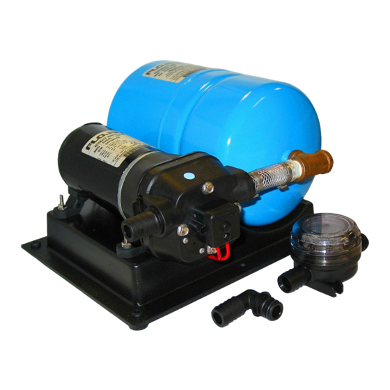
Sfoglia online o scarica il pdf Informazioni sull'installazione e sull'assistenza per Attrezzatura marina FLOJET 2840 Series. FLOJET 2840 Series 4. Rv/marine water booster system
WARNING: DISCONNECT POWER TO PUMP AND OPEN VALVE TO
!
RELIEVE WATER PRESSURE PRIOR TO SERVICING PUMP
9
Key
Part No.
Description
0
20409-043
Service Kit*
1
20404-003
Upper Housing Assy Kit
2
20407-030
Check Valve Kit - EPDM
w/O-Ring & Ferrules
3
20403-040
Diaphragm Kit, Santo
w/Pistons & Screws
4
20419-002
Lower Housing
5
02009-080A Motor 12 Volt DC 2840-100
02009-087A Motor 12 Volt DC 2840-110
02009-073A Motor 12 Volt DC 2840-120
02019-027A Motor 24 Volt DC 2840-300
02049-026A Motor 32 Volt DC 2840-400
02029-091A Motor 115 Volt AC 2840-000
"
20799-000A Accumulator Tank
*Service Kit includes #2, #3, #8 and drive cam assembly.
DISASSEMBLE
Pressure Switch (9)
1. Disconnect power to pump and open a faucet or valve to
relieve system pressure.
2. Remove the two visible Pressure Switch Screws located on
each side of the Pressure Switch (9). DO NOT ADJUST
ALLEN HEAD SCREW IN CENTER OF SWITCH.
Upper Housing (1)
3. Loosen but DO NOT remove the four Pump Head Screws and
carefully remove Upper Housing Assembly (1).
4. Slide Port Clip (8) back and unplug from Tank Plumbing.
5. Remove Check Valve (2) and inspect for debris.
Check Valve Assembly (2) Follow Steps 1, 3 & 4
6. Inspect Check Valve (2) and O-Ring
Lower Housing (4) Follow Step 1
7. Remove pump from both Base and Tank Plumbing.
8. Remove Rubber Feet by pulling out and sliding to the rear
and follow step 3.
9. Rotate Lower Housing (4), so access Rubber Grommet foot
notch is aligned with Cam Bearing Set Screw (4-C), loosen
set screw with a 1/8" Allen Wrench and slide pump head off
shaft.
motor
Diaphragm (3-B)
10. Loosen four cam piston screws with Phillips head screw
driver and pull apart cam (4-B) from Inner Pistons (3-A). (Both
pistons (3-A & C) should be replaced when a new Diaphragm
(3-13) is installed.)
Motor (5) Follow Steps 1, 7, 8 & 9
1
2
B
A
8
6
Qty
1
1
1
1
1
1
1
1
1
1
1
C
3
4
A
Key
Part No.
Description
" 120796-000A Base
6
20381-022
Port Kit - (set of 2)
Hose Barb, 90° 3/4"
Hose Barb, Straight 3/4"
7
20406-002A Pump Head Assy.
8
20408-000
Port Clips (Set of 2)
9
02090-118
Pressure Switch - 40 PSI Off, Sealed
"
04325-143A Complete MPU w/Strainer - 12V 4.5 GPM
"
04305-144A Complete MPU w/Strainer - 12V 3.5 GPM
"
04305-500A Complete MPU w/Strainer - 12V 3.3 GPM
"
04325-343A Complete MPU w/Strainer - 24V 4.5 GPM
"
04325-443A Complete MPU w/Strainer - 32V 4.5 GPM
"
04325-043A Complete MPU w/Strainer - 115V 4.5 GPM 1
"
01740-000
Strainer, Inline 3/4" Hose Barb
REASSEMBLE
Diaphragm (3-B)
1. Insert Outer Pistons (3-C) into Lower Housing (4-A) by
bending pistons at center fold.
2. Placing the Diaphragm (3-B) (flatter side of Diaphragm facing the
motor) on the Lower Housing (4-A). Press each Inner Piston (3-A)
through the Diaphragm and Lower Housing (4-A) into Outer
Piston (3-C). Hex stem of Inner Pistons (3-A) must be aligned into
hex holes in Outer Pistons (3-C). Tighten cam piston screws
partially, center piston in diaphragm, and tighten screws securely
(18 in. lbs. torque). Also, the Outer Pistons (3-C) must be aligned
with alignment slots on Cam Assembly (4-B) making sure screw
holes align in cam assembly, otherwise diaphragm will leak.
Cam Bearing (4-B)
3. Place Cam Bearing (4-B) over Inner Pistons (3-C) and tighten
down with four Phillips Head Screws. (18 in. lbs. torque)
Lower Housing (4) to Motor (6)
Coat motor shaft with grease prior to installing Cam Bearing
(4-B).
4. When installing the Lower Housing (4), rotate mounting foot
notch to align with Cam Bearing Set Screw (4-C).
5. Attach Cam Bearing (4-B) to motor shaft indentation with
Cam Bearing Set Screw (4-C). (35 in. lbs. torque)
6. Reinsert Rubber Feet.
Check Valve (2)
7. Place Ferrules (Rubber Cones) in the Upper Housing (1)
coned side first.
8. Properly seat O-Ring in Check Valve (2) and insert Check
Valve (2) into the Upper Housing (1).
Upper Housing (1)
9. Place Upper Housing (1) on top of the Lower Housing (4-A)
and tighten Hex Bolts (30 in. lbs. torque) through the Upper
Housing (1) to the Motor.
5
D
C
B
7 Includes items 1 thru 4
!
Qty
1
1
1
1
1
1
1
1
1
1
1
1