Bobike Maxi+ Istruzioni per l'utente - Pagina 6
Sfoglia online o scarica il pdf Istruzioni per l'utente per Accessori per biciclette Bobike Maxi+. Bobike Maxi+ 9.
element with key 13, with the flat side against the
rear fork. Ensure that the socket is mounted hori-
zontally and with the T-shaped opening facing
upwards.
B Mounting using the ATB bracket
Secure the ATB bracket (J) with the supplied
screws, the brackets and the plastic washers to
the saddle tube. To do this, take the large bracket
together with the plastic washer and the long
screws, and place these on the saddle tube from
the front. Then take the other plastic washer and
the small bracket and place these to the rear
side of the saddle tube. Now mount the brackets
to each other using the screws and the supplied
Allen key. Hand-tighten the screws, because the
correct position must still be set. Now mount the
plastic socket using the two short screws between
the bracket. Ensure that the correct side (opening)
is pointing upwards and hand-tighten the screws.
2
Now secure both locking units (L) to the rear fork
approximately 30 cm below the socket (I). The loc-
king units are suitable for rear forks with a diameter
of between 12 and 25 mm. To adjust, insert the
clamp bracket of the locking unit in the first, middle
or rearmost slot.
Ensure that both locking units left and right are
secured at exactly the same height. Hand-tighten the
screws and the turn the knobs so as to create a slot
of about 1 cm.
3
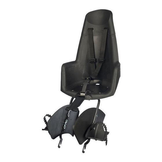
The foot straps (F) must be fitted to the footrests (E)
before mounting. Mount the foot guards (K) and the
foot supports onto the footrest tube (D).
Adjust the height of the footrests
To set the correct height of the footrests (E), first
measure the length of your child's lower legs from
the underside of the knee to the sole of the foot. This
measurement must match the distance from the seat
to the underside of the footrest. This then gives the
height at which the footrests must be mounted.
Mounting the foot guards
Place one foot guard on the inside of the footrest
tube. Place a footrest on the outside of the support
www.bobike.com
tube and slide the long screw through the washer,
the footrest, the support tube and the foot guard.
Ensure that the elasticised band of the safety belt,
which is attached to the footrest tube, is not trapped
between the foot guard and the footrest tube. The
elasticised band belongs in the uppermost position
below the seat. Secure the nut plate to the inside of
the foot guard, parallel to the support tube. Now
tighten the screw firmly with a torque of 3 Nm.
Mount one of the short screws together with the
washer and the nut plate as far from the footrest as
possible, so that the foot guard sits securely. After
the other foot guard and footrest have been moun-
ted, you can place your seat on your bicycle.
Wheel contact guard
If you bicycle does not have a baggage carrier
then mount the extra wheel contact guard to the
foot guards. You can click this securely to the foot
guards. If the extra wheel contact guard also fits on
your bicycle with a baggage carrier, then secure the
guard as well.
4
Take the seat and insert the head of the mounting
bracket (C) straight and all the way into the socket.
5
Turn the footrest tube down, fit the ends into the
locking units and tighten the knobs. Ensure that the
outer ends of the footrest tubes are placed in the slot
as far as possible.
6
When adjusting the seat, the surface of the seat must
not tip forwards. The child could slide out of it. It is
recommended to angle the seatback slightly towards
the rear. Ensure that a space of at least 1 cm
remains between the seat and the baggage carrier
or the mudguard. The seat is correctly mounted
when the footrest tubes are at an angle of between
60 and 80 degrees. If the position of the seat is still
not right then move the locking units up or down, or
adjust the position of the ATB bracket (J) or the soc-
ket (I). When the correct position is reached, tighten
the locking units and the screws of the ATB bracket
or the nut of the socket with a torque of 10 Nm.
Tighten the short screws in the plastic socket until the
slack is taken up. The steel pin and the lock ensure a