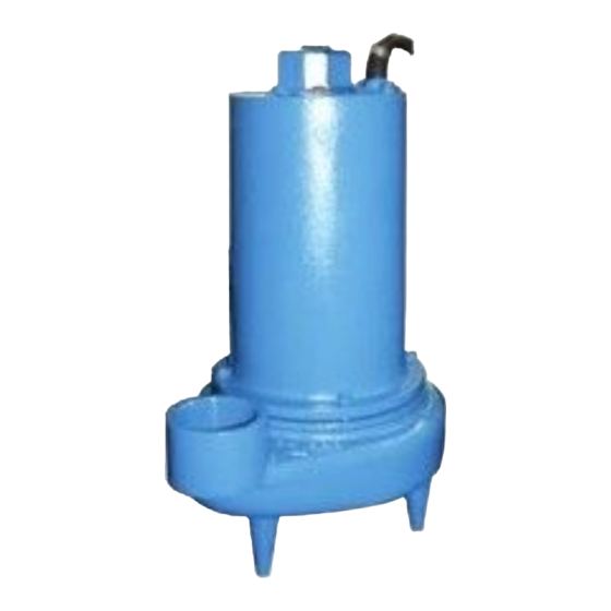
Barnes 3SE-DS Series Manuale di installazione e funzionamento - Pagina 8
Sfoglia online o scarica il pdf Manuale di installazione e funzionamento per Apparecchiature industriali Barnes 3SE-DS Series. Barnes 3SE-DS Series 17. Submersible sewage ejector
Anche per Barnes 3SE-DS Series: Manuale di installazione e funzionamento (20 pagine), Manuale di installazione e funzionamento (18 pagine)

F-1.4) Pressure Test:
Motor Housing - Before checking the pump for leaks around
the shaft seal, square rings, and cord inlet, the oil level should
be full as described in section F-1.3. Remove pipe plug (19)
from motor housing (5).Apply pipe sealant to pressure gauge
assembly and tighten into hole (see Fig. 2). Pressurize motor
housing to 10 P.S.I. Use a soap solution around the sealed
areas and inspect joints for "air bubbles". If, after five minutes,
the pressure is still holding constant, and no "bubbles" are
observed, slowly bleed the pressure and remove the gauge
assembly. Replace the pipe plug (19) using a sealant. If the
pressure does not hold, then the leak must be located and
repaired.
Seal Chamber - Remove pipe plug (19) from spacer (50) and
check that the seal chamber is full of oil. Apply pipe sealant to
pressure gauge assembly and tighten into hole in spacer (50).
Pressurize seal chamber to 10 P.S.I. and check for leaks as
outlined above.
Caution ! - Pressure builds up extremely
fast, increase pressure by "tapping" air
nozzle. Too much pressure will damage
seal. DO NOT exceed 10 P.S.I.
10 PSI AIR
REMOVE PIPE PLUG
FIGURE 2
F-2) Impeller and Volute Service:
F-2.1) Disassembly and Inspection:
To clean out volute (24) or replace impeller (29), disconnect
power, remove hex nuts(12), and lockwasher (11), vertically lift
motor and seal plate assembly from body (24). Clean out body
if necessary. Clean and examine impeller (29), for pitting or
wear and replace if required, inspect gasket (10) and replace
if cut or damaged. If the impeller (29) needs replacing, remove
nut (3), place a flat screwdriver in the slot of the end of the
shaft to hold the shaft stationary while unscrewing the impeller
(29).
F-2.2) Reassembly:
To install impeller (29), screw impeller onto the shaft hand tight.
Clean the threads with Loctite cleaner. Apply thread locking
compound to shaft threads and install nut (3). Torque to 40 ft.
lbs. Rotate impeller to check for binding.
10 PSI AIR
PRESSURE GAUGE ASSY
(SEE PARTS LIST)
REMOVE PLUG
Position gasket (10) on volute flange and position impeller and
motor housing on volute (28). Position lockwasher (11) on cap
screw (12) and screw into volute (28). Torque to 8 ft. lbs. Check
for free rotation of motor and impeller.
F-3) Motor and Bearing Service
F-3.1) Disassembly and Inspection:
To examine or replace the motor (20) and bearings (6) and
(42), disassemble volute and impeller as outlined in paragraph
F-2.1. Drain oil from motor and seal chamber as outlined
in paragraph F-1.3. Disassemble shaft seal as outlined in
paragraph F-4.1.
Position unit upright, using blocks to avoid resting unit on
shaft. Remove socket head cap screws (9). Vertically lift the
outside motor housing (5) from seal plate (52) by lifting eye
(17). Inspect square ring (8) for damage or cuts. Remove cable
assembly (30) by unscrewing gland nut (30a), gland nut (32a),
and hex nut (16) from motor housing (5). Remove cable lead
wires from motor lead wires and sensors wires from control
cable by disconnecting connectors (23) and (40). The unit
voltage should be noted. Remove the motor bolts and lift motor
(20) from seal plate (52). Examine bearing (6) and replace if
required. If replacement is required, remove retaining ring (2)
then remove bearing (6) from motor shaft using a wheel puller
or arbor press.
Vertically lift motor stator from rotor. Inspect bearing (42),
belleville washers (43) and spacer (44) if replacement is
required, remove belleville washers (43) and spacer (44) from
motor shaft, remove bearing (42) from motor shaft using a
wheel puller or arbor press. Inspect winding for shorts and
check resistance values. To test the temperature sensor (if
equipped), check for continuity between the black and white
wires. If found to be defective contact a motor service station
or Barnes Pumps service department. Check rotor for wear. If
rotor or the stator windings are defective, the complete motor
must be replaced. Check motor capacitor (21), on single
phase units and replace if defective. Check moisture sensors
(46) for damage and replace if necessary.
Important ! - ALL parts must be clean before
reassembly.
F-3.2) Reassembly:
Bearings - When replacing bearings, be careful not to damage
the rotor or shaft threads. Clean the shaft thoroughly. Apply
adhesive compound to the shaft and press bearing (6) on the
motor shaft, position squarely onto the shaft applying force to
the inner race of the bearing only, until bearing seats against
the retaining ring (2).
Apply adhesive compound to the other end of motor shaft
and press bearing (42) on, positioning squarely on the shaft
shoulder, applying force to inner race of bearing only. Position
belleville washer (43), spacer (44) and another belleville
washer (43), with curvatures pointing away from spacer (44),
on motor shaft above bearing (42) and lower motor stator over
rotor.
8
