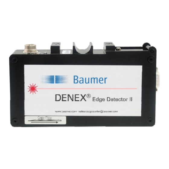
Baumer DENEX Edge Detector II Manuale d'uso - Pagina 7
Sfoglia online o scarica il pdf Manuale d'uso per Accessories Baumer DENEX Edge Detector II. Baumer DENEX Edge Detector II 20.

3.3.2.1 Output Signal – Connections
The output can be used for both "current source" and "current sink" depending on what is
required by the equipment. In current source mode, the sensor output will give a positive
pulse to the stacker/totalizer when active. In current sink mode, the sensor output will give
a negative pulse. Figure below shows a common 24 VDC as power supply and feeding the
pulse. It is possible to have different power supplies. In that case, the 24V power is
connected to pins 1 and 6, and the totalizer can be connected to pins 2 and 5.
Figure 3.3.2.1.1 Electrical connection, common 24V-supply. Current source (PNP).
Figure 3.3.2.1.2 Electrical connection, common 24V-supply. Current sink (NPN).
Copy Sensor
Figure 3.3.2.1.3 Electrical connection, separate supply for power and pulse.
User Manual DENEX Edge Detector II
7/20
Baumer Electric AG
Version 2013-02, V1.6
www.baumer.com
Frauenfeld, Switzerland
