Amprobe CT-326-C Manuale d'uso - Pagina 11
Sfoglia online o scarica il pdf Manuale d'uso per Strumenti di misura Amprobe CT-326-C. Amprobe CT-326-C 20. Current tracer
Anche per Amprobe CT-326-C: Manuale (2 pagine)

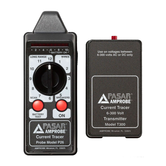
Receiver Test Position
1. To test the receiver's battery, push the "Battery Test" button. If the LED display does not light
up within the "Battery OK" area, replace the battery and repeat.
2. Turn the receiver's range switch to "Breakers-5."
3. Press "ON" and wait 2 seconds for the receiver to calibrate. Holding the calibrated receiver,
touch its tip to the front and center of the operating transmitter (see Fig. 1). Ten LEDs will
flash brightly, in sequence from left to right, at the same rate as the transmitter's LED,
indicating that the receiver is working correctly. This flashing LED response from the probe is
what you will be looking for as you trace circuits.
Circuit breakers, Fuses
1. Plug the transmitter into an outlet, or attach with the insulated clip leads of the pigtail
connector to the conductors you want to identify.
2. Turn the receiver's range switch to "scan-5."
3. Press the receiver's "ON" button and wait for it to calibrate
4. Wave the receiver's tip slowly outside the closed panel box door and observe the receiver's
signal. As the probe approaches the correct panel box, the audio indication becomes louder
and the LEDs will flash. Use the receiver's earphone, If necessary, to hear the signal.
5. The correct panel box produces the strongest signal. Not all LEDs need to flash in order to
signal the correct panel. However, if the probe's signal is of equal intensity on more than
one panel, the gain may be set too high. Turn the range switch to a lower setting, I.e.,
"Breakers-3."
6. Open the panel box door.
7. Turn the receiver's range switch to "Breakers-4."
8. Press the receiver's "ON" button and wait for it to calibrate.
9. Touch the receiver's tip to each circuit breaker as shown in Fig.3
10. The receiver's tip must be held at the correct angle to the breaker to ensure accuracy. As the
receiver approaches the correct breaker, the audible indicator becomes louder and the LEDs
will flash.
11. The breaker controlling the circuit being traced produces the strongest signal. Not all LEDs
need to flash in order to signal the correct breaker. However, if the receiver's signal is of
equal intensity on more than one breaker, the gain may be set too high. Turn the range
switch to a lower setting, i.e., "Breakers-3" or "Wires-2."
12. Remove the panel trim.
13. Turn the receiver's range switch to "Wires-1."
14. Press the receiver's "ON" button and wait for it to calibrate.
15. Touch the receiver's tip on the wire connected to breaker previously identified. The receiver's
tip must be held at the correct angle to the wire to ensure accuracy. Only the wires that the
transmitter is attached to will produce a signal.
1.800.561.8187
9
www.
.com
