Amprobe CT-326-C Manuale d'uso - Pagina 9
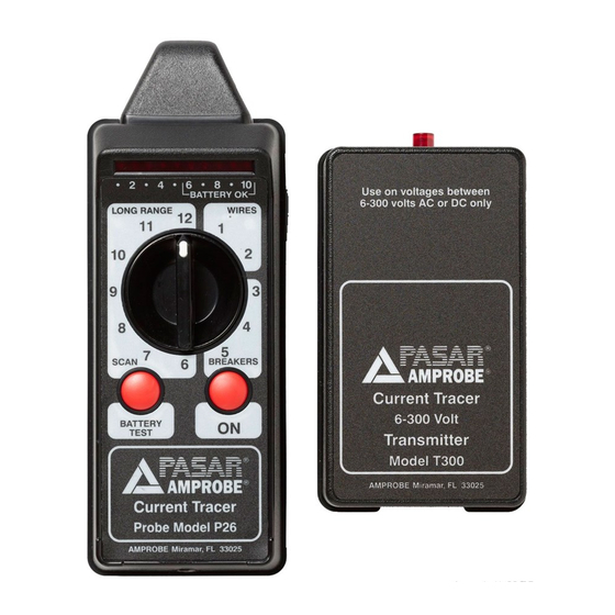
Sfoglia online o scarica il pdf Manuale d'uso per Strumenti di misura Amprobe CT-326-C. Amprobe CT-326-C 20. Current tracer
Anche per Amprobe CT-326-C: Manuale (2 pagine)

oPERATIoN
Transmitter Test Position
IMPoRTANT: For locating and tracing
applications, always use a voltmeter to
determine the line voltage before connecting
the transmitter.
1. Plug the transmitter into any standard
electrical outlet (see Fig.1). If there is no
outlet available, use the pigtail connector
provided.
2. Verify that the transmitter's red LED is
blinking.
3. If the LED is not blinking, confirm whether or
not the outlet is energized with a voltmeter.
The transmitter must be able to draw current
in order to operate.
4. If the LED is not blinking and the outlet has
been confirmed to be energized, remove
the Transmitter from the outlet and check
the fuse located on the LED end of the
transmitter. The transmitter may have an
open fuse if it has been attached to voltages
higher than its range.
Receiver Sensitivity
The receiver's range switch determines the
probe's gain - receiver sensitivity depends on
three elements:
1. Angle of the receiver: The receiver's tip must
be held perpendicular to the conductor in
order to allow the conductor's magnetic
field and the receiver's sensor to couple most
effectively.
2. Position of the range switch: If the probe
displays 10 LEDs, the gain is too sensitive
(except in the test position). Turn the range
switch to a lower setting.
3. Battery: Change the probe's battery if the
battery test does not cause the LEDs to light
within the "Battery OK" area.
1.800.561.8187
7
www.
.com
Fig.1
Strong Signal
Weak Signal
Receiver probe's tip must be
perpendicular to the wire
Fig.2
