AirStage UTY-RHKY Manuale di installazione - Pagina 3
Sfoglia online o scarica il pdf Manuale di installazione per Telecomando AirStage UTY-RHKY. AirStage UTY-RHKY 8. Uty-rhk series
Anche per AirStage UTY-RHKY: Manuale operativo (2 pagine), Manuale operativo (20 pagine)

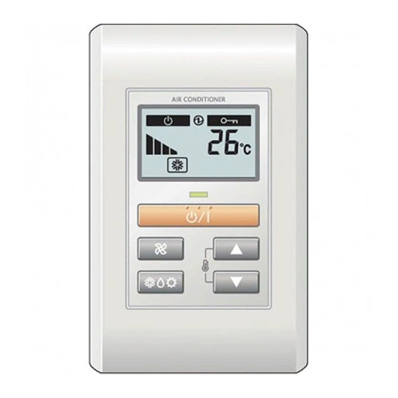
4.2. Name of parts
Display panel
3
• Display panel
6
8
"
" (START/STOP Button)
1
"
" , "
2
"
" (Fan Control Button)
3
Operation Lamp Indicator
4
Electric energy Indicator
5
Standby Indicator
6
Operation Lock Indicator
7
Fan Speed Indicator
8
Temperature Indicator
9
Error Indicator
0
Operation Mode Indicator
A
5. INSTALLING THE REMOTE CONTROLLER
Always use the accessories and specifi ed installation work parts. Not
using the specifi ed parts will cause units to fall off, electric shock, fi re, etc.
Install at a place that can withstand the weight of the unit and install
positively so that the unit will not topple or fall.
During installation work, do not permit children or users to approach. It will
cause injury or electric shock.
Before starting installation work, turn off the power of indoor unit power
supply. Do not turn on the power again until installation is completed.
Otherwise, it will cause electric shock or fi re.
Use the attached cable. If extending or branching, implement suitable
measures. When connecting the cables to the terminal, make sure to
connect securely. Improper installation work may cause electric shock,
fi re, or heat.
Install the remote controller cables securely to the terminal block. Confi rm
that external force is not applied to the cable.
If insertion fi xing are imperfect, it will cause electric shock, or fi re, etc.
Perform functional earthing work positively. Do not connect the functional
earthing wire to a telephone functional earthing wire, water pipe, or
conductor rod.
Always fasten the outside covering of the connection cable with the cable
tie. If the insulator is loose, short circuit may occur.
When performing cable wiring work, be sure that it does not touch the
user. It will cause injury or electric shock.
4
1
2
5
7
9
10
11
" (Set Temperature Button)
WARNING
Do not set the DIP switch of this unit except as specifi ed in this manual
or the operating manual supplied with the air conditioner. Setting the
switches other than specifi ed will cause an accident or trouble.
Use an insulated screwdriver to set the DIP switches.
Before opening the case of this unit, completely discharge static electricity
charged on you body. Not doing so will cause trouble.
Do not touch the PC board and PC board parts directly with your hands.
Otherwise, injury or electric shock could result.
Tightening the mounting screws too tight will damage the case of this unit.
Be careful so that the front case does not fall after the front case screws
are removed. Otherwise, injury could result.
Install the remote controller cables 1 m away from television and radio to
avoid distorted images and noise.
Make sure water and insects do not enter the unit. Use putty, etc., as a
countermeasure to gaps that may provide a route of ingress. Water and
insects may cause malfunction, electric shock, or fi re.
Confi rm the name of each terminal block of the unit and connect the
wiring in accordance with the directions given in the manual so that there
is no incorrect wiring. Improper wiring work will damage the electric parts
and cause smoke and fi re.
When installing the remote controller cable near a source of
electromagnetic waves, use shielded cable. Otherwise, a breakdown or
malfunction could result.
5.1. Installation
Insert the end of a fl at blade screwdriver at the
of the rear case and remove the rear case top by turning the screwdriver.
Be careful to avoid breaking the cable by over-tightening the cable tie.
When connecting the remote controller cables, do not overtighten the
screws.
(1) Pass the remote controller cable through the hole in the rear case
and connect the remote controller cable to the remote controller
terminal block specifi ed in Fig. 1.
(2) Clamp the remote controller cable sheath with the binder as shown in
Fig. 1.
CAUTION
of the groove at the side
CAUTION
En-2
