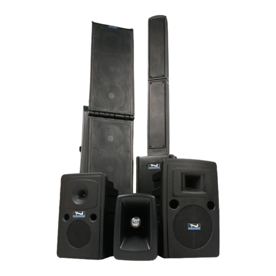
Anchor bigfoot Manuale d'uso - Pagina 2
Sfoglia online o scarica il pdf Manuale d'uso per Impianto stereo Anchor bigfoot. Anchor bigfoot 13. Line array sound system
Anche per Anchor bigfoot: Manuale di avvio rapido (2 pagine), Manuale di avvio rapido (2 pagine), Manuale di avvio rapido (2 pagine)

Bigfoot® Sound System Owners Manual
BASIC SYSTEM OPERATION
NOTE: Fully Charge Batteries Before First Use!
1. Unfold Line Array
2. Set all Input Levels to minimum & Tone Controls to
flat (middle) setting
3. Plug wired microphone into the MIC 1 or MIC 2 jacks
and/or any audio source into the LINE-IN jacks
4. Switch POWER to ON, Power ON LED will light
5. Slowly increase Level Controls for active Input Jacks
to desired volume
6. Adjust Tone Controls for desired sound quality
IMPORTANT: Make all connections with shielded cables to avoid
hum, buzzing or interference.
OPENING BIGFOOT LINE ARRAY
1. Unhook rubber latch on bottom
2. Carefully move upward to open position
3. Attach both rubber latches
IMPORTANT: Latches MUST be locked and grill MUST
face forward for system to work!
CLOSING BIGFOOT LINE ARRAY
1. Turn POWER to OFF
2. Unlock both rubber latches
3. Fold Array to closed position
5. Close Array latch
CD/MP3 COMBO PLAYER
UNIVERSAL MIC – INPUT JACKS
Balanced XLR – low impedance, for balanced mic,
powers condenser-type mics.
Unbalanced 1/4" – high impedance, for unbalanced
mics, no phantom power.
LINE IN – INPUT JACKS
1/4" and 1/8" (3.5mm) is used to hook
up a portable CD player, iPod, Laptop
or other external audio source.
LINE OUT – OUTPUT JACK
Record your presentation or connnect
to another powered sound system
(Daisey-Chaining together
multiple Bigfoot Speakers).
USB DC OUT - 5V 500 mA
To charge/power external device.
TONE CONTROLS – BASS/TREBLE
For System Setup & Operation Videos Visit Our Website: www.anchoraudio.com
BACK PANEL OF BIG-8000CU4
(see page 4)
Balanced 1/4"
POWER SWITCH
Power On LED
Green - power on
CHARGE STATUS INDICATOR
MADE IN USA
SIX YEAR WARRANTY
WIRELESS RECEIVERS
(see page 5)
BLUETOOTH RECEIVER
(see page 7)
AC POWER CORD INLET
BATTERY LEVEL INDICATOR
2
