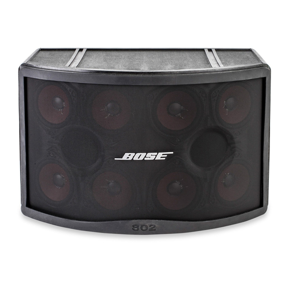
Bose 802 C II Manuale d'uso - Pagina 2
Sfoglia online o scarica il pdf Manuale d'uso per Altoparlanti Bose 802 C II. Bose 802 C II 22. System controllers
Anche per Bose 802 C II: Manuale di servizio (20 pagine), Manuale di servizio (23 pagine)

WARNING
To reduce the risk of fire or electrical shock, do not
expose this system to rain or moisture.
CAutIoN
To reduce the risk of electrical shock, do not
remove the cover of the 40
systems controllers. There are no user-serviceable
parts inside. Refer servicing to qualified service
personnel. The caution markings described here
are located on the top cover of the 40C and 80C
II systems controllers.
The lightning flash, with arrowhead
symbol within an equilateral triangle,
is intended to alert the user to the
presence of uninsulated "dangerous voltage" within
the system enclosure that may be of sufficient
magnitude to constitute a risk of
electrical shock.
The exclamation point within an
equilateral triangle, as marked on
the system, is intended to alert the
user to the presence of important operating and
maintenance instructions in this owner's guide.
WARNING
The Bose
40C and 80C II systems controllers are
®
electrical appliances. There are no user-serviceable
parts inside. As with all electrical appliances,
dangerous electrical shock may result if repair
is attempted by unqualified personnel. Service
and the installation of any optional electronics
should always be performed by Bose-authorized
personnel.
C or 80
C II
TM
®
Contents
.0
Before You Begin ........................................... 3
.0
Safety Information .......................................... 3
3.0
Introducing The Controllers............................ 4
4.0
Sound System Configurations ........................ 4
4.
Basic Configurations ............................ 4
4.
System II Loudspeaker ........................ 5
5.0
General Operating Instructions ...................... 9
5.
Unpacking ............................................ 9
5.
Controller Parts ..................................... 9
5.3
Input Connections ..............................
5.4
Output Connections ...........................
5.5
Mechanical Connections .................... 3
5.6
Basic Operation ................................. 3
Appendices
Protection Circuit Harness .................. 6
Systems Controller ............................. 8
A.3
Appendix B: Specifications ................................... 0
And Controls ....................................... 0
Mechanical Specifications ................. 0
B.3
Controller Accessories ....................... 0
Appendix C: Warranty And Service ......................
C. Warranty Period ..................................
C.3 Contacting Bose Corporation .............
Cannon
®
TM
