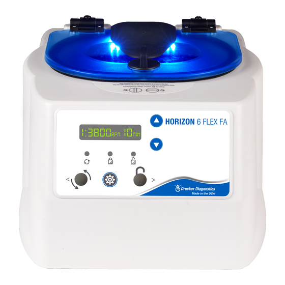
Drucker Diagnostics Horizon 6 FA Manuale di servizio - Pagina 6
Sfoglia online o scarica il pdf Manuale di servizio per Apparecchiature diagnostiche Drucker Diagnostics Horizon 6 FA. Drucker Diagnostics Horizon 6 FA 10.

7.4. Rotor Nut
•
If the rotor Nut needs to be tightened, use a ½" nut driver and tighten it by hand
until snug.
•
Rule of thumb: One full thread showing above the nut is a good indicator of proper
installation.
7.5. Speed Calibration
•
Check the centrifuge speed periodically, every two years is recommended.
•
Important: When verifying rotor speed, make certain that all carriers are installed
in the rotor.
•
No calibration adjustment of speed can be made, only a verification of rotor speed.
7.6. Removing the Cabinet (Upper Housing)
•
There are nine screws that fasten the centrifuge cabinet to the base.
•
Begin by unplugging the centrifuge and waiting 10 minutes for internal voltages to
dissipate.
•
Use a #2 Phillips screwdriver to remove the cabinet screws (six on the bottom,
three in the rear)
•
The centrifuge control panel is attached to the base internally with cable
harnesses. Be careful not to stress the cables when removing the cabinet.
•
Lift the cabinet straight up and off the base, setting it down on its front side.
•
Gently remove the combination power supply / motor harness from the control
board.
7.7. Replacing the Lid Lock Assembly
•
The lid lock assembly is accessible once the cabinet has been removed.
•
Gently remove the lid lock wire harness' from the control board.
•
The lid lock assembly is held in place with four screws.
•
Two #8-16 screws on the inside and two #8-32 screws on the outside (covered by
the open/close label).
•
Remove the Open/Close label to access the two screws underneath.
•
To install, line up the holes on the lid tray assembly to the screw holes on the
cabinet and install the four screws.
•
Complete the installation by plugging the wire harness into the control board
header 'J2'.
DRUCKER DIAGNOSTICS
HORIZON 6 SERVICE MANUAL
SM024
REV A
6
