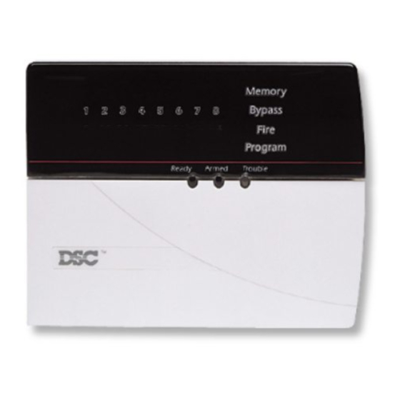
DSC PC5100 Manuale di istruzioni per l'installazione - Pagina 8
Sfoglia online o scarica il pdf Manuale di istruzioni per l'installazione per Sistema di sicurezza DSC PC5100. DSC PC5100 12. 2-wire addressable device interface module

P
R
O
G
R
3.4 Module and Device Supervision
To confirm that the panel is supervising the PC5100, enter section
[903]. If the PC5100 is being supervised, on LED keypads light 15 will
be on, and on LCD keypads the message "PC5100" will be displayed.
Devices are supervised as zones. The level of supervision for AML
devices is determined by the type of zone supervision that was se-
lected for the PC5010/5015 (i.e. normally closed, single end of line, or
double end of line supervision).
For more information, please refer to your PC5010 or PC5015 Installa-
tion Manual .
3.5 Removing Devices
Before removing devices from the system, you must delete their serial
numbers. To remove a 2-wire addressable device from the system,
perform the steps outlined in Section 3.2. Enter [00000] for the serial
number of the device you wish to remove.
You may need to power down the panel to clear troubles which
could be caused by deleted devices.
3.6 Replacing Devices
In order to replace an AML device, you must first remove the old
device, as described in section 3.5, above. Then, enroll the new device
as described in section 3.2.
3.7 Programming Section Descriptions
Sections [01] - [32]: Zone Serial Numbers
These sections are for enrolling the serial numbers of each 2-wire
addressable device on the system. See Section 3.2 for details.
Section [97]: Special Functions
Option 1: Walk test light ON. Turn on this option to enable the walk
test LED on all motion and glassbreak detectors. If a device is working,
its LED will turn on when it is tested.
This option does not turn on the walk test - only the walk test
LEDs. To walk test the system, follow the instructions in the
Walk Test section of the PC5010 or PC5015 Installation Manual.
• To test the motion detectors, create motion in front of each device. If
the LED turns on, the device is working.
• To test the glassbreak detectors, you will also need to turn on option
4 (Glassbreak Test ON). See the AMA-100 Installation Instruction
sheet for testing instructions.
Once the walk test has been completed, re-enter Section [97] and turn
option [1] OFF.
Option 2: Smoke test on installer exit. Turn on this option to enable
the smoke test for all AML smoke detectors. The PC5100 will begin the
test after you exit from Installer's Programming. The PC5100 tests each
smoke detector by:
• turning on the test output of each detector, and then checking for an
alarm state on each detector
A
M
M
I
N
G
6
T
H
E
P
C
5
1
0
0
