Auber Instruments JSL-64A Manuale di istruzioni - Pagina 2
Sfoglia online o scarica il pdf Manuale di istruzioni per Timer Auber Instruments JSL-64A. Auber Instruments JSL-64A 5. 1/32 din general purpose timer

AUBER INSTRUMENTS
Note B. Pin 10 is the common pin for the pin 6/7/8. There are two ways to
operate terminal 6, 7, and 8.
a) Connecting a normally open (NO) momentary push button switch between
the pin (6, 7 or 8) to the COM (10). Please note, the function starts when you
release (or open) the button of the switch, not when you press down the switch.
See Figure 5.
b)
Connecting a DC logic signal (TTL or CMOS or voltage in the range from 3
to 30 VDC) between the terminal
function is rising-edge triggered. The logic signal should normally be at high
level. The function starts when the signal goes from low to high. If you have an
inverted logic signal, you need to connect a NPN transistor between terminal
and COM; add 10Kohm resistor to the gate for signal input.
The function of all these terminals is accomplished by the rising phase of
control signal. If the control signal is from a momentary NO switch that is
connected to the terminal, the action starts when switch is released (from close
to open). When the control signal is from another digital device, the action
starts when voltage goes from low to high.
Note C. Pin 9 is a special terminal reserved for Espresso Shot Timer function
(when FUNC is set to EST) in the JSL-64A and JSL-64A-EST. When it is
connected with the COM pin, the timer resets its display and start counting up
from zero. When it is disconnected from COM pin, the counting stops.
5. Getting Started
5.1 Powering up the timer
To power up the timer, simply connect 120 VAC or 220 VAC power to pin 1
and 2. It is recommended to use a power supply or power cord that has an
ON/OFF switch on it.
5.2 General operations
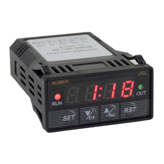
A brief description of the keys on the timer are described below. Please also
refer to Section 6 for details of parameter RUN, STOP, and PAUS. The
settings of these parameters can affect the actual functions of STP, PAU, and
RST key.
Key
SET
• Shot-press: bring up the set value; select parameter; save
value.
• Long-press: bring up the parameter menu.
• No action while timer is running.
▼/STP
• Stops the timer from counting time.
• May stops the relay output depending on the STOP setting.
• Decrease value.
▲/PAU
• Pauses the timer counting.
• Increase value.
RST
• Clears timer display.
• May restart the timer if parameter RUN = RST.
2021.03
(6, 7 or
8) to the COM (10). Please note, the
See Figure 6.
Action
5.3 Accessing the parameters
To bring up the parameter menu, long press the SET key for 3 seconds till the
display shows "FUNC". Use UP or DOWN arrow key to scroll the parameter list.
Use SET key to select or check the value of a parameter. Use UP or DOWN
arrow key to change the value of any parameter, and press the SET again to
save the new value then go back to the parameter list.
Please refer to the Section 6 for the details of each parameter. Figure below
shows how to access the menu.
Long-press
for 3
SET
seconds
SET
SET
SET
Figure 3. Flow chart of how to change the parameter values.
5.4 Changing the set values
Depending on the timer function you choose, you may need to adjust the set
values T1 and T2.
If you use the Single Delay function (FUNC = SDL), you'll need to adjust T1. If
you use Delayed Interval or Cycle function (FUNC = DINT or CYCL), you'll
need to adjust T1 and T2. If you use the Espresso Shot Timer function (FUNC
= EST), you don't need to adjust the set values. The flow chart below shows
how to adjust the set values.
Normal Display
Mode
1:10
Short-press
SET
SET
T1
END
SET
Figure 4. Flow chart of how to change set values on the timer.
WWW.AUBERINS.COM
Set Value
Change the set value
(blinking)
using UP or DOWN
arrow key
1:10
1:00
P2/5
