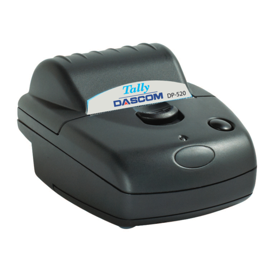
Dascom DP-520 Manuale d'uso - Pagina 8
Sfoglia online o scarica il pdf Manuale d'uso per Stampante Dascom DP-520. Dascom DP-520 12. Wired printer
Anche per Dascom DP-520: Manuale dell'operatore (19 pagine), Istruzioni per la configurazione rapida (2 pagine), Istruzioni per la configurazione rapida (2 pagine)

RS-232 SERIAL INTERFACE
The DT-520 has an industry standard RS-232 interface. The default parameters are 9600 baud, 8 data
bits, 1 stop bit and no parity. Other baud rates can be programmed by control codes, or by using a setup
utility. Contact Dascom Technical Support for information regarding the setup utility.
Serial data is expected in standard RS-232C format with -12V meaning 'mark' or '1' and +12V a logical '0',
with reference to the common ground. The serial data output line, TxD, transmits XON/XOFF and status
information to the host at the same Baud rate and in the same format as the serial data input. The
hardware busy line is true (nominal -12V) when busy. Both serial output lines will relax to approximately
0V when the printer is in sleep mode, and the user must allow a short period after awakening before
relying on the values of these signals.
Some host equipment use a constant space condition (+12V) to indicate a reset condition or wait state.
Some battery powered host equipment present the same output signal when they go to sleep. The printer
can be set to ignore this condition as detailed in the Programmer's Manual, but even then this type of host
behavior may result in one or more spurious characters being received and printed.
CONNECTOR DETAILS
The printer has two user connectors shown below:
Charger Input
CONNECTOR PINOUTS
Charger Input Socket Detail
Pin
Dimension (mm)
Inner
Inside
Ø 2.5
Outer
Outside Ø 5.5
The maximum insertion length is 12 mm.
6
INTERFACE DETAILS
CONNECTIONS AND EMC PRECAUTIONS
Function
Positive / Charger Input
Negative / 0V Common
Pin 1
RJ12 Combined Data Socket
