Benedini TBS Mini Manuale - Pagina 3
Sfoglia online o scarica il pdf Manuale per Apparecchiature di registrazione Benedini TBS Mini. Benedini TBS Mini 11. Digital multifunctional rc-soundunit
Anche per Benedini TBS Mini: Manuale (11 pagine), Manuale dei dati tecnici (11 pagine)
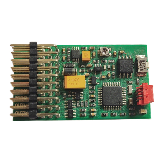
2. Connection
Plugs (from top to bottom)
1. 8 Ohm speaker or ext. amplifier
2. Prop1 Input (Speed IN)
3. Prop1 Output (Speed OUT)
4. Prop2 Input (Receiver), optional
5. Prop3 Input (Control channel)
6. PWM1 (Servosignal 1) or Out 10
7. PWM2 (Servosignal 2) or Out 11
8. Out 1+2 switching output
9. Out 3+4 switching output
!!! ORANGE (or white) signal lead always on TOP !!!
Speaker
PROP 1
/ Ampl.
In
Speaker
Signal
Plus
(Input)
Speaker
Power
Minus
Ground
Ground
Speaker connection:
If a speaker is connected directly at the TBS Mini, make sure using the Speaker Plus and Speaker
Minus pins (upper two ones). You must NOT use the Ground pin at the speaker connector!
Use 8 Ohm speaker.
Switching outputs (Out 1..4, Out10, Out11)
All outputs are switching to NEGATIVE of the receiver supply voltage. PLUS is available at the
center pins of the according plugs.
Out 10 is available at the PWM1 plug
Out 11 is available at the PWM2 plug
TBS Mini, 05/2016
Watch plug orientation
PROP 1
PROP 2
Out
In
Signal
Signal
(Output)
(Input)
Power
Power
Ground
Ground
PROP 3
PWM 1
In
(OUT10)
Signal
Signal
(Input)
(Output)
Power
Power
Ground
Ground
www.benedini.de
Learn Button
Prog. Cable
Top: Signal (orange)
Center: Power (red)
Bottom: GND (black)
PWM 2
OUT
(OUT 11)
1+2
Signal
OUT 2
(Output)
(negative)
Power
Power
Out 1
Ground
(negative)
Page 3 of 11
OUT
3+4
OUT 4
(negative)
Power
OUT 3
(negative)