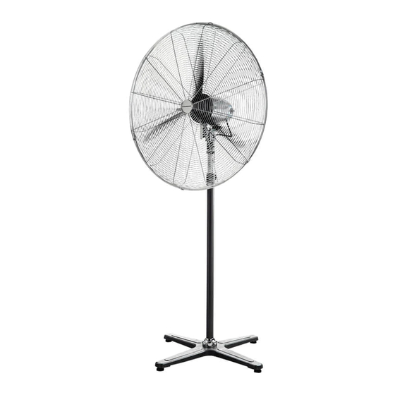
DYNABREEZE FA-23105 Manuale d'uso e garanzia - Pagina 6
Sfoglia online o scarica il pdf Manuale d'uso e garanzia per Ventilatore DYNABREEZE FA-23105. DYNABREEZE FA-23105 12. Industrial 750mm pedestal fan
Anche per DYNABREEZE FA-23105: Istruzioni e manuale d'uso (12 pagine)

USING YOUR DYNABREEZE FAN
UNPACKING AND BUILDING THE FAN
1. Unpack the unit from box that your
unit was purchased in and recycle the
packaging if possible.
2. Check that all the parts are included on
the unit and nothing is broken. If you
require assistance, please contact the
place of purchase.
3. Attach the pedestal stand column to the
pedestal stand base and secure with the
provided bolt and spring washer by using
a spanner or socket.
4. Unscrew and take out the height
adjustment locking bolt from the pedestal
stand column.
5. Slide the height adjustment bolt cover
down the column to rest on the pedestal
stand base.
6. Pull out the pedestal column extension
tube inside the pedestal column and refi t
the height adjustment locking bolt and
cover.
CAUTION: The locking bolt must be fully
tightened before continuing to assembling
the motor section to the pedestal stand.
7. Fit the electric motor to the pedestal
stand and tighten the bolt.
CAUTION: The bolt must be fully tightened
before the fan is operated.
6 DYNABREEZE INDUSTRIAL STRENGTH FAN
8. Set the rear safety grille in position and fi x
it in position using the 4 provided bolts,
until tight.
9. Install the blade onto the electric motor
shaft and screw the blade retaining bolt
until tight.
10.Open clips on the front safety grille and
place front safety grille onto rear safety
grille (align locking screw holes) and close
clips.
11. Secure both guards fi rmly by fi tting and
tightening the locking screw and nut.
FIRST USE AND OPERATION OF THIS FAN
1. Read and follow this manual and adhere
to all safety precautions.
2. Plug the power cable into a suitable
power outlet and switch on the power
outlet.
3. Set the fan on a fi rm, level dry surface.
4. The Oscillating Control: The oscillating
structure is shown in the diagram, it can
be adjusted in the angle from 0°-90°.
When adjusting screw is moved to the
direct axle, the fan will not oscillate. The
longer – the distance from the adjusting
to the direct axle is, the larger the
oscillating angle will be.
NOTE: Always switch o and unplug the unit
from the power outlet before changing the
oscillating angle. Loosen the adjusting screw
on the oscillating control turn the fan to the
desired angle.
