Galaxy DX 88HL Manuale d'uso - Pagina 6
Sfoglia online o scarica il pdf Manuale d'uso per Radio Galaxy DX 88HL. Galaxy DX 88HL 10. Full channel am/fm/ssb mobile built in frequency counter am/fm 10w-ssb 25w with roger beep
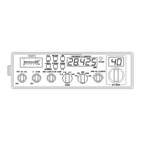
5. MIC GAIN (inner dual concentric): Adjusts the microphone gain in
the transmit and PA modes. This controls the gain to the extent that full
talk power is available several inches away from the microphone.
6. RF GAIN CONTROL (outer dual concentric): Use to reduce the gain
of the RF amplifier under strong signal conditions.
7. BAND SELECTOR: This switch selects A, B, C, D, E, F, G or H band
of operation.
8. MODE (PA/FM/AM/USB/LSB): This switch is used to select PA, FM,
AM, LSB or USB mode of operation. Unless the station with which
communication is desired is equipped with SSB, the AM or FM mode is
normally used. The mode selector switch changes the mode of operation
of both transmitter and receiver simultaneously. Turn to "Receiving SSB
signals" for a further explanation of single sideband.
9. CLARIFIER: Allows variation of the receiver operating frequencies
above and below the assigned frequency. Although this control is
intended primarily to tune in SSB signals, it may be used to optimize
AM/FM signals as described in the Operating Procedure paragraphs.
Coarse operates both TX/RX but Fine only in RX.
10. CHANNEL SELECTOR: This switch selects any one of the forty
channels desired. The selected channel appears on the LED readout
directly above the Channel Selector knob.
11. METER: This meter indicates received signal strength, transmitter RF
output power and SWR level.
12. +10KHz FREQUENCY SHIFT SWITCH: When switch is pressed the
frequency is shifted 10KHz up. On following channels. A channel can
be used by setting this switch to +10KHz position.
Normal
3
7
11
15
19
13. ROGER BEEP SWITCH: When this switch is placed in the ROGER
BEEP position, your radio automatically transmits the audio sign at the
end of your transmission. The listener can note easily that your
transmission is over.
+10KHz
3A
7A
11A
15A
19A
- 9 -
14. POWER SWITCH: To select Hi (10 Watts) or Lo (3 Watts) power in
AM or FM transmission only.
15. OFF-NB/ANL SWITCH: In the NB/ANL position, the RF noise
blanker is activated and automatic noise limiter in the audio circuits is
also activated. The RF noise blanker is very effective for repetitive
impulse noise such as ignition interference.
16. COUNTER SWITCH-ON/OFF: Depressing this switch causes the
receiver and transmitter frequency to be displayed on the frequency
counter.
17. BAND SWITCH: This switch is used to select Hi or Lo Band selection.
18. FREQUENCY COUNTER: This frequency counter indicates of the
selected channel you wish to operate on.
19. RECEIVE/TRANSMIT INDICATOR: The receive/transmit LED
indicator is located next to the channel indicator. When in receive, the
LED will be green. When in transmit the LED will be red.
20. CHANNEL INDICATOR: Numbered LED indicates the selected
channel you wish to operate on.
- 10 -