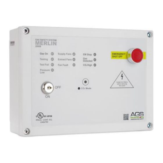
AGS Merlin 2000S Manuale d'uso - Pagina 4
Sfoglia online o scarica il pdf Manuale d'uso per Rivelatori di gas AGS Merlin 2000S. AGS Merlin 2000S 12. Gas proving and ventilation interlock system
Anche per AGS Merlin 2000S: Manuale di installazione e funzionamento (12 pagine), Manuale di installazione e funzionamento (12 pagine)

Merlin 2000S
2
Circuit Board Terminals
2.1
LINE VOLTAGE
A 110-120VAC electrical supply should be externally fused at
3A and connected to the terminals marked [LINE VOLTAGE
LNE].
2.2
VALVE OUT
The 110-120VAC gas solenoid valve should be powered using
the terminals on the Merlin 1000S detailed [VALVE OUT LNE].
2.3
SUPPLY FAN & EXTRACT FAN PD SWITCHES
These terminals are used to receive an input signal from external air pressure switches or external
current monitors. These are linked out as a factory setting as shown.
2.4
BMS OUT
Terminal connections are available on the circuit board for connections to
Building Management systems.
This is a relay that changes state in alarm or when gas is on/off and can be
used in conjunction with the [12VDC] output and other external relays that
affect other devices and controls such as purge fans, audible alarms etc.
Detailed on the circuit board as [BMS OUT] normally closed (N/C),
common (COM) and normally open (N/O). These are volt free
connections.
2.5
PRESSURE SENSOR
The terminals marked pressure sensor [+ - IN].
These wire to the gas pressure sensor which is
screwed into the downstream port on the gas
solenoid valve.
Min Operating Pressure = 0.17psi
Max Operating Pressure = 1.45psi
ENSURE THIS IS SCREWED TO THE DOWNSTREAM PORT OF THE GAS SOLENOID VALVE
Rev: 06
05-19
Wiring to switches & current monitors should be made using
two-core volt free connections.
If only one fan is being used the terminals not in use should be
left linked out.
User Guide
4
