Jandy CS250 Manuale di installazione e funzionamento - Pagina 6
Sfoglia online o scarica il pdf Manuale di installazione e funzionamento per Filtro per piscina Jandy CS250. Jandy CS250 16. Single element cartridge pool & spa cs filters
Anche per Jandy CS250: Manuale di installazione e funzionamento (16 pagine)
Page
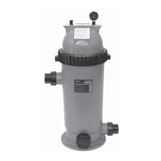
Outlet Port
13"
20 1/8"
Inlet Port
Figure 2.
Dimensions, CS Cartridge Series Filter
- Top View
Section 3.
Installation Instructions
WARNING
Use equipment only in a pool or spa installation.
Do not connect system to an unregulated city water
system or other external source of pressurized water
producing pressures greater than 35 psi.
3.1 Filter Location
1.
Select a well-drained area, one that does not flood
when it rains. Damp, non-ventilated areas should
be avoided.
2.
Provide solid mounting for the filter and pump
system. Install system on a concrete slab or solid
concrete blocks to avoid risk of settlement. Do not
use sand to level the filter as the sand will wash
away. Filter systems can weigh up to 300 lbs.
3.
Install electrical controls at least five (5) feet from
the filter. This will allow enough room to stand
away from the filter during start-up.
4.
Allow sufficient clearance around the filter to
permit a visual inspection of the clamp ring (see
Fig. 3).
Drain
Port
14 1/8"
WARNING
Water discharged from an improperly positioned filter
or valve can create an electrical hazard which can
cause death, serious injury or property damage.
CAUTION
Maintain your pressure gauge in good working order.
The pressure gauge is the primary indicator of how
the filter is operating.
5.
Allow sufficient space above the filter to remove
the filter lid and filter element for cleaning and
servicing.
6.
Position the filter to safely direct water drainage.
Align the air release valve to safely direct purged
air or water.
7.
If the filter is to be installed below the water level
of the pool, isolation valves should be installed on
both the suction and return lines to prevent back
flow of pool water during any routine servicing
that may be required.
3.2 Filter Preparation
1.
Check carton for damage due to rough handling
in shipment. If carton or any filter components are
damaged, notify carrier immediately.
2.
Carefully remove the accessory package. Remove
the filter tank from the carton.
3.
A visual inspection of all parts should be made
now. See parts list in Section 9.
4.
Install the pressure gauge and adapter assembly to
the threaded hole marked "Pressure Gauge" at the
top of the filter (see Fig. 4).
5.
Install the air release valve into the threaded
opening marked "Air Release" at the top of the
filter (see Fig. 4).
NOTE
Teflon tape is included in the accessory bag.
6" Minimum Clearance
Filter
Figure .
Filter location - Top View
Drain
12" Minimum
Clearance