Jandy CS250 Manuale di installazione e funzionamento - Pagina 7
Sfoglia online o scarica il pdf Manuale di installazione e funzionamento per Filtro per piscina Jandy CS250. Jandy CS250 16. Single element cartridge pool & spa cs filters
Anche per Jandy CS250: Manuale di installazione e funzionamento (16 pagine)
Cartridge Filters - CS Series Filter
Pressure
Gauge
Pressure
Gauge
Adapter
Figure .
Pressure Gauge and Pressure Release
Assembly
3.3 Filter Installation
1.
This filter operates under pressure. When the
locking ring is properly seated and the filter is
operated without air in the water system, this filter
will operate in a safe manner.
2.
If the system can be subjected to higher pressures
than the maximum working pressure of the lowest
rated component, install an ASME approved
automatic Pressure Relief Valve or Pressure
Regulator in the circulation system.
3.
Place the filter on the concrete pad, lined up with
the inlet and outlet pipes.
4.
To reduce pressure losses, 2" (minimum) piping
is recommended for plumbing the system.
Jandy Heater
Waterfall
Pool Return
Figure 5.
Basic Pool/Spa Combination Plumbing
Air Release
Valve
Spa Make Up
Jandy
Check
Valve
Never exceed the manufacturer's maximum
recommended filter flow rates.
5.
For best efficiency use the fewest possible number
of fittings. This will prevent a restriction of the
water flow.
6.
Make all plumbing connections in accordance with
local plumbing and building codes. Filter unions
are provided with an o-ring seal. Use silicone
based lubricants on the o-rings to avoid damage.
Do not use pipe joint compound, glue or solvent
on union threads.
7.
Keep piping tight and free of leaks. Pump suction
line leaks may cause air to be entrapped in filter
tank or loss of prime at the pump. Pump discharge
line leaks may show up as equipment pad leaks or
air being discharged through the return lines.
8.
Support the inlet/outlet pipes independently to
prevent any undue strains.
9.
Place the union nut over the pipe and connect
the pipes to the union tailpieces using PVC
glue. Do not use teflon tape or pipe dope on any
union threads. Put the o-ring in the tailpiece and
assemble the unions to the filter tank.
10. Drill pilot holes into the equipment pad with a ¼"
masonry bit. Use the holes in the tank bottom base
as a guide.
11. Install ¼ x 2¼" Stainless Steel Tapcon® screws
and tighten.
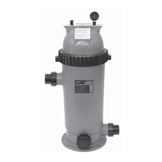
Drain
Outlet
Inlet
Port
Port
Jandy Filter
From Pool
Drain
Spa Return
From Pool Skimmer
Page
Inlet Port
Jandy Pump
Spa Suction