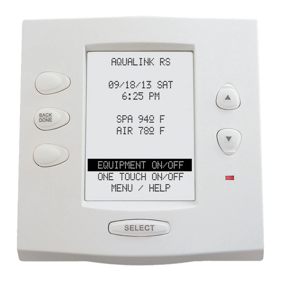
Jandy AquaLink RS6 Manuale di installazione - Pagina 6
Sfoglia online o scarica il pdf Manuale di installazione per Pannello di controllo Jandy AquaLink RS6. Jandy AquaLink RS6 16. Dual equipment systems

- 1. Section 2. System Overview
- 2. Plumbing Diagrams
- 3. Connecting Power and Mounting Bezel
- 4. Connecting Control Panel Cable to Pcb
- 5. Section 3. Power Center Connection (Low Voltage)
- 6. Dip Switch Functions
- 7. Dip Switch Settings for Pool and Spa Combination
- 8. Section 5. Dual Equipment Wiring Diagram
Page 6
Section 2. System Overview
2.1
Package Contents
Package contents will depend on which AquaLink
RS System you are installing. All Jandy AquaLink
RS Systems come complete with the appropriate
number of 3HP relays needed.
Control System Sub-Assemblies
All Button Dual Equipment
OneTouch Dual Equipment
All Button Control Panel, Power Center PCB,
OneTouch Control Panel, Power Center PCB,
Three (3) Temp Sensors,
Three (3) Temp Sensors,
Additional Relays when necessary
Additional Relays when necessary
Power Centers
Standard Power Center
PureLink Power Center (with mounting brackets),
(with mounting brackets),
4-3 HP Relays, RS Transformer,
4-3 HP Relays, and RS Transformer
AquaPure Transformer, and AquaPure PCB's
PureLink Sub-Panel Power Center (with mounting
brackets) 4-3 HP Relays, RS Transformer,
Sub-Panel Power Center (with mounting brackets),
Breaker Mount Plate, GFCI Knockout, AquaPure
4-3 HP Relays, RS Transformer, Breaker Mount Plate,
Transformer, and AquaPure PCB's
and GFCI Knockout
