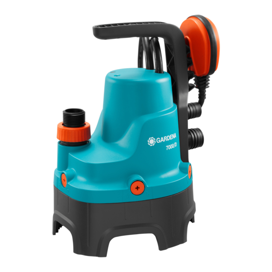
Gardena 7000/C Manuale dell'operatore - Pagina 5
Sfoglia online o scarica il pdf Manuale dell'operatore per Pompa dell'acqua Gardena 7000/C. Gardena 7000/C 13. Clear water submersible pump / dirty water submersible pump

To connect the hose [ Fig. I4 ]:
(1)
(2)
1. Put the connection
,
outlet of the pump.
3. OPERATION
The pump can be operated in both automatic and manual
modes.
Automatic operation [ Fig. O1 ]:
(5)
The float switch
turns the pump on automatically when
the water level exceeds the cut-in height and the water is
pumped out. The float switch
as soon as the water level falls below the cut-out height.
1. Stand the pump on a firm surface
– or –
use a rope attached through the bore hole
carrying handle to immerse the pump in a well or
shaft. During automatic operation, ensure that the float
(5)
switch
can move freely.
2. Connect the power cable into a mains socket.
To adjust the cut-in and cut-out height [ Fig. O2 ]:
The cut-in height and cut-out height (see 7. TECHNICAL
DATA) can be adjusted.
v Press the cable of the float switch
(7)
the float switch lock
.
• To ensure the pump is switched off safely, always fix the
cable of the float switch in place in one of the three float
switch locks on the pump handle.
4. MAINTENANCE
DANGER! Electric shock!
Risk of injury due to electric shock.
v Disconnect the product from the mains before
you do maintenance.
The GARDENA Clear Water Submersible Pump / Dirty
Water Submersible Pump should not require regular main-
tenance.
To flush the pump:
After pumping pumped chlorinated swimming pool water
or other liquids leaving residues, the pump should be
flushed with clear water.
1. Immerse the pump in clear water.
2. Flush the pump with clear water.
5. STORAGE
To put into storage:
v The product must be stored away from children.
v Clean and stowe the product in a frost-free place before
the first frost arrives.
12
(3)
(4)
or
with the collar
on the
(5)
turns the pump off again
(6)
in the
(5)
into an opening in
2. Tighten the collar
(4)
.
3. Connect the hose with the connection.
• Do not select a cable length that is too long or short to
ensure that the float switch can turn on and off properly.
• The higher the opening of the float switch lock
higher the cut-in and cut-out height.
• The shorter the length of cable between the float
(5)
switch
and the float switch lock
cut-in height and the higher the cut-out height.
• The cable length between the float switch
(7)
float switch lock
must always be at least 10 cm.
Manual operation [ Fig. O3 ]:
The minimum residual water depth (see 7. TECHNICAL
DATA) is only achieved in manual mode because the float
switch already switches off the pump before this when in
automatic mode.
(5)
1. Push the float switch
with the cable downward.
2. Stand the pump on a firm surface
– or –
use a rope attached through the bore hole
carrying handle to immerse the pump in a well or shaft.
3. Connect the power cable into a mains socket.
The pump remains in constant operation because the float
switch is bypassed.
To clean the suction base and the feed impeller
[ Fig. M1 / M2]:
1. Unlock (counterclockwise) the 5 turn-locks
a screwdriver.
2. Remove the suction base
(11)
3. Loosen the nut
.
4. Remove the feed impeller
5. Clean the suction base
(9)
(12)
6. Put the washer
and the feed impeller
shaft.
(11)
7. Screw the nut
on the motor shaft.
(9)
8. Put the suction base
9. Lock (clockwise) the turn-locks
Disposal:
(in accordance with RL2012/19/EC)
The product must not be disposed of to normal
household waste. It must be disposed of in line with
local environmental regulations.
(7)
, the
(7)
, the lower the
(5)
and the
(7)
onto the float switch lock
(6)
in the
(8)
with
(9)
.
(10)
(12)
and the washer
.
and the feed impeller
(10)
.
(10)
on the motor
on the pump.
(8)
with a screwdriver.
