Fronius 63A-1 Manuale rapido - Pagina 7
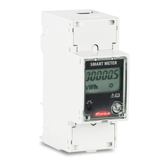
Sfoglia online o scarica il pdf Manuale rapido per Sistema di saldatura Fronius 63A-1. Fronius 63A-1 20. Smart meter
Anche per Fronius 63A-1: Manuale rapido (17 pagine), Manuale di avvio rapido (2 pagine), Manuale di avvio rapido (2 pagine), Manuale di avvio rapido (8 pagine), Manuale di avvio rapido (10 pagine)
Modbus termination switch on the Datamanager 2.0 and the GEN24 inverter:
The internal bus termination 120-Ohm resistance (for Modbus RTU) needs to
be switched to ON. This switch is set to ON by default.
Please Note:
The termination resistance must be activated for the first and last device in an RS485 bus.
2.2 Activating the Fronius Smart Meter on the SnapINverter
It is recommended to complete the Solar.web Wizard first and get the system online. Once
completed please go to Section 2.2.1 for the Fronius Smart Meter activation.
If the system is not being set up for online monitoring the Fronius Smart Meter can be
activated within the Technician Wizard as per Section 2.2.2.
2.2.1 Activating the Fronius Smart Meter in the SnapINverter Web Interface
The PV Inverter homepage can be accessed in two ways:
1. Via the Wi-Fi Access Point:
-
Activate the Wi-Fi Access Point on the Datamanager card (inverter screen under Setup) or
Datamanager Box 2.0
-
Connect your computer/table/smart phone to the Fronius_240.XXXXXX network
-
Open a web browser and go to http://192.168.250.181.
Alternatively you can use the Fronius SolarWeb App (Tablet/Smart Phone), open the Solar.web app
and select Settings. Then select "PV Inverter Homepage" or "Your System Monitoring" depending
on your device.
2. Via the LAN Port:
-
Connect your computer to the Datamanager via LAN cable
-
Switch the Datamanager IP Switch to Position 'A'
-
Open a web browser and go to
Once connected follow the below steps:
(c) Fronius International GmbH, 2020
120 Ω termination
switch
http://169.254.0.180
7/19