Packing List, Accessories, and Tools Needed
Before installing your unit, confirm that your package includes the following items. If any parts
are missing, contact your Garmin dealer immediately.
Standard Package
•
GXM 51 Antenna
•
Surface-mount bracket
•
Pole-mount bracket
•
Under-deck mount bracket
•
Mounting hardware (screws and adhesive
pads)
•
NMEA 2000 T-connector
•
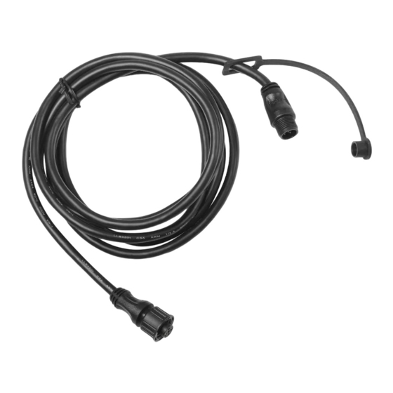
NMEA 2000/audio cable 19 ft., 8 in. (6 m)
•
Audio adapter cable 1 ft. (30.5 cm)
•
Installation instructions
Optional Accessories
•
Additional NMEA 2000 network
components
•
Audio adapter cable extensions
Step 1: Mount the GXM 51 Antenna
You can surface mount the GXM 51 antenna, attach it to a standard 1 in. OD pipe-threaded-pole
marine mount (14 threads-per-inch—not included), or even install the antenna under fiberglass.
Select a suitable location for the GXM 51
antenna on your boat. To ensure the best
reception, mount the GXM 51 antenna in a
location that has a clear, unobstructed view of
the sky in all directions.
•
Avoid mounting the GXM 51 antenna
where it is shaded by the superstructure of
the boat, a radome antenna, or a mast.
•
On a sailboat, avoid mounting the GXM 51
antenna high on the mast.
•
The GXM 51 antenna provides more-stable
reception when located nearer to water
level.
•
Mount the GXM 51 antenna at least 3.3 ft. (1 m) away from (preferably above) the
path of any radar beam or a VHF radio antenna.
Temporarily secure the antenna in the preferred mounting location and test it for correct
operation. If you experience interference with other electronics, try a different location. After
verifying correct operation, permanently mount the antenna.
Tools Needed
•
Drill
•
Drill bits—
/
in. (3 mm) and
1
8
(19 mm)
•
Hole saw, 1 in. (25 mm)—surface-mount
cable hole
•
Screwdriver—surface-mount screws
•
Pencil (to mark surface-mount pilot holes)
•
Countersink bit (when mounting on
fiberglass)
•
Marine sealant (for some mounting
options)
Better
Better
EMI
EMI
EMI (Electromagnetic Interference)
EMI (Electromagnetic Interference)
from engine components
from engine components
Above - best
Above - best
Below - OK
Below - OK
Radar
Radar
GXM 51 Placement Considerations
GXM 51 Placement Considerations
GXM 51 Installation Instructions
/
in.
3
4
Best
Best
Good
Good
3 ft.
3 ft.
(1 m)
(1 m)
VHF Radio Antenna
VHF Radio Antenna

