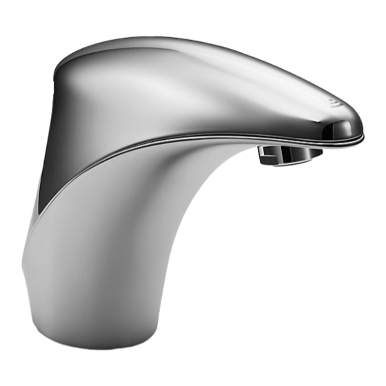
Kohler Elosis 18057T-B-CP Manuale di istruzioni per l'installazione - Pagina 5
Sfoglia online o scarica il pdf Manuale di istruzioni per l'installazione per Apparecchiature per il bagno Kohler Elosis 18057T-B-CP. Kohler Elosis 18057T-B-CP 12. Sensor faucet

技术参数
电源:直流 4节5号碱性电池(LR06×4)
交流 电压220V,频率50/60Hz
检测时间:小于0.5秒
关阀延时:0.5~1秒
感应距离:自动调节
流量:水压为0.3MPa 时,流量不大于2.0L/min
超时用水控制:超时用水1分钟,自动止水。
环境温度:1 ~55
进水温度:0.5~71
适用水压:0.05~
安装步骤
如何安装水龙头
一 龙头与面盆的安装固定
将固定螺杆(2)安装到水龙头(1)底部
处。再把垫片(3)套在固定螺杆上。并
嵌入水龙头底部的盘槽中。然后将电
源线(7)和进水软管(8)穿过安装孔,从
面盆下方将固定橡胶垫片(4)固定金属
垫片(5)和固定螺母(6)对齐固定螺杆向
上套入。调整水龙头电源线及进水软
管的位置。用扳手拧紧固定螺母以便
把水龙头固定在面盆上。
二 安装控制组件
拧下控制盒盖(10)螺钉(11),打开控制
盒(9),根据安装尺寸图(图一)在墙
壁合适的位置钻孔,打入膨胀管
(12),使控制盒紧贴墙面,再用螺钉
(13)将其固定在墙壁上。
注意:控制盒长边端需竖直放置,出
水口位置可根据需要左右调整。
将软管(16)一端与三通进水软管组件
(17)连接,另一端与控制组件(15)进水
口连接,再将出水口与龙头出水软管
(14)连接,三通进水软管组件另外两端
与角阀(18)连接。
对于单冷龙头,将软管一端与滤网接头
(19)相连,另一端与角阀连接即可。
1248536-T01-C
℃
℃
PARAMETERS
Power: DC 4 pieces of AA size alkaline batteries
AC 220V, 50/60Hz
Senser Duration: Less than 0.5s
Shut-off Delay: 0.5~1s
Sensing Distance: Automatic adjustment
Flow Rate: No more than 2.0L/min at 0.3MPa.
Overtime Flowing Control: Automatically stop flushing when
the faucet senses an object for more than 1 minute
continuously
Ambient Temperature: 1~55℃
Supply Water Temperature: 0.5~71℃
Supply Water Pressure: 0.05~0.86MPa
2
1
3
4
6
5
7
8
9
10
图一
13
12
INSTALLATION
How to Install the Faucet
1. Fasten faucet on lavatory:
Install the stud (2) to the underside of the
faucet (1). Slide the gasket (3) over the
stud, and then seat the gasket in the groove
on the underside of the sprout. Cross power
cord (7) and water inlet hose (8) through
mounting hole, slide rubber washer (4),
metal washer (5) and nut (6) onto the stud
from under the sink. Adjust faucet power
cord and water inlet hose position, fasten nut
to secure faucet on lavatory mounting
surface by wrench.
2. Install Control Assy.
Unscrew valve cover (10) screw (11)
by screwdriver,
open
(9). Determine proper mounting location
11
per rough –in (Fig 1), then punch
expansion tube (12) in. Place valve box
against the wall and then secure control
valve assembly on the wall by bolts (13).
Note: place the long end of control box
upright, water outlet position shall be
adjusted left/right based on requirements.
Connect hose (16) to Tee water inlet
hose assembly(17), and then connect
water outlet with faucet water outlet
hose (14). Connect Tee water inlet hose
other two ends with valve (18).
For cold water faucet, connect hose
to the cylinder(19) and then connect
with valve.
valve
cover
5
