DeZurik POWERRAC R1 Manuale di istruzioni - Pagina 14
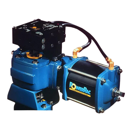
Sfoglia online o scarica il pdf Manuale di istruzioni per Controllore DeZurik POWERRAC R1. DeZurik POWERRAC R1 20. Spring-return actuator used on 1/2-3" pec eccentric valves
DeZURIK
Actuator Reassembly
15. Tighten the jam nut (B22) finger-tight.
16. Mount the end cover (B17) and the gasket (B16) to the housing studs (B18) with the four nuts
(B20) and lockwashers (B19) and tighten the nuts to 15 ± 2 foot pounds (20 ± 3 Nm).
Mounting Actuator
Refer to Figure 5 for component identification.
1. Determine which of the four actuator-to-valve mounting positions is desired, as shown on the
Valve Installation Drawing.
2. Match the open or closed position of the valve with the open or closed position of the actuator.
3. Note the position of the word "open" on the top cover (B11).
4. Position the cover on the housing (B1) so that dial hash mark for "open" will be parallel with the
pipeline when the valve is installed.
Note: One or more of the steps below may be required, depending upon the mounting position
selected, the type of valve shaft, and the positions of the valve, actuator, and actuator cover.
Rotate the valve shaft.
Stroke the actuator.
Select a different actuator-to-valve mounting position.
Remove and re-index the actuator cover:
Remove the four cover screws (B15), rotate the cover, and replace the four cover screws
(B15) and washers (B14). Tighten the screws to 15 ± 2 foot pounds (20 ± 3 Nm).
5. Place the gasket between the actuator and the valve, engage the actuator with the valve shaft in
the desired mounting position as determined in step 1, and slide the actuator onto the valve
shaft.
Note: Certain high-temperature valves include and require a high-temperature gasket (B28). If
the valve includes a gasket, use the gasket included with the valve rather than the gasket
included with the actuator.
6. Assemble the four actuator mounting screws (B26) with lockwashers (B27) up through the
mounting holes in the actuator adaptor on the valve, through the gasket (B28), and into the
threaded holes in the bottom of the actuator, then tighten the screws (B26) to 15 ± 2 foot
pounds (20 ± 3 Nm).
7. Adjust the open and closed position stops. See "Position Stops" section.
8. Operate the actuator and valve three full cycles to demonstrate that the unit operates smoothly
in both directions.
Note: Do not exceed 100 psi (690 kPa) in cylinder.
D10389
(Continued)
Page 14
November 2020