DFE SW6 Manuale di istruzioni per l'uso - Pagina 8
Sfoglia online o scarica il pdf Manuale di istruzioni per l'uso per Controllore DFE SW6. DFE SW6 20. Digital tension controller

1.1 MAIN INTERFACE DESCRIPTION
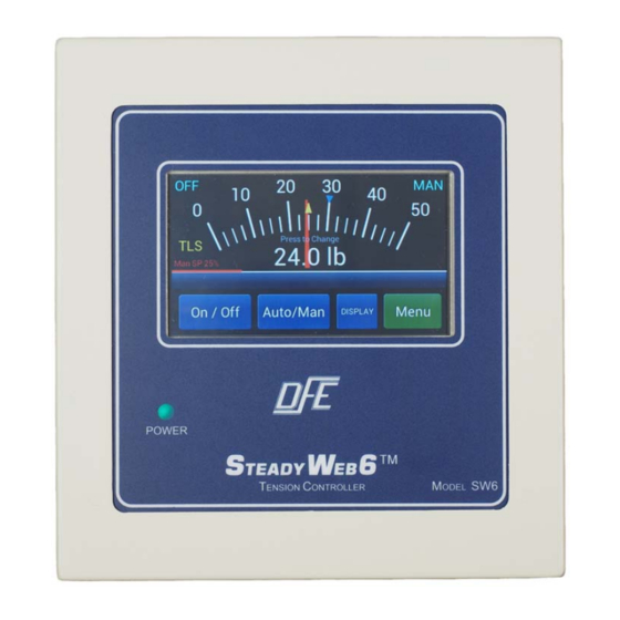
Figure 2 – LOCATIONS OF TOGGLE BUTTONS / INDICATORS IN DISPLAY
All screens, settings and adjustments which are not primarily tension-displaying functions require some on-
screen navigation to access them.
The remaining button in the lower right hand corner of the screen is green and displays as either "Menu",
"Back" or "Save" depending on what screen is current, and is used to advance to other menus, to back out
of menus, or to save selections or adjustments.
Green buttons on menu screens indicate
selectable functions. When there are more
buttons in a menu than fit on the menu screen, the
excess buttons are off-screen, but the menu
screen may be shifted to reveal them by pressing
arrow buttons at one or both ends of the screen
(Fig. 3). If there are no arrows at the end of the
screen, then there are no off-screen buttons to
reveal.
Holding a green button down will bring up
related information, which effectively serves as an
on-screen manual.
Grey buttons indicate functions that may not be
selected until certain conditions are met. If in
doubt about why a button is grey, it may be pressed and held to view the explanation. Sometimes meeting
the necessary conditions requires permission-based access and actions in accordance with the Technical
Reference Manual (DFE P/N 801-2540).
On navigation screens, pressing the Back button will return the prior screen. If the Back button has been
replaced with another function, the use of which is not desired, the screen may be exited via the Display
button instead.
In the unlikely event of a screen failure, an always-on Power LED (Fig. 1) on the front of the controller will
inform the operator if the unit is still powered up.
1.2 DISPLAY MODE DESCRIPTIONS
To display the tension setpoint, real time tension and related process information, the Tension Display
mode should be used when making product, and the Menu Display mode should generally be used when
making changes to the process. When in Tension Display mode, pressing the Menu button will switch to
the Menu Display mode. Likewise, when in Menu Display mode, pressing the Display button will return the
screen to Tension Display mode.
TENSION DISPLAY MODES: Two different screens are available in Tension Display mode. Tension can
either be displayed as a momentary value on an analog meter (Fig. 4) or as tension vs. time in a trend-line
plot (Fig. 5) and may be toggled back and forth by pressing the Display toggle button.
Operator-adjustable display settings include Tension Update Time, Display Damping, Plot Update
Time, Line Speed Display, Diameter Display and Display Brightness, the adjustments of which are
described in Section 2.2, DISPLAY ADJUSTMENTS.
2
continured...
Figure 3 - SCREEN SHOWING SIDE ARROWS
