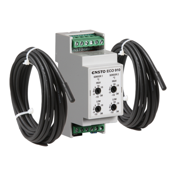
ensto ECO910 Manuale di istruzioni per il funzionamento - Pagina 7
Sfoglia online o scarica il pdf Manuale di istruzioni per il funzionamento per Termostato ensto ECO910. ensto ECO910 17. Frost protection thermostat

ECO910 FROST PROTECTION THERMOSTAT
ENG
1. INTRODUCTION
The ECO910 is a device for the control of frost protection in outdoor areas, ramps, roofs and rainwater
systems. There is no main switch in the product but it has to be placed elsewhere in the circuit. A residual
circuit breaker has to be used according to the local installation regulations (see Fig. 2).
2. INSTALLATION
The device should be installed on the DIN rail in accordance with Figs. 1 and 2.
3. OPERATION
The set values of the thermostat are adjusted by rotating the adjusting wheels with a screwdriver (Fig. 3).
Frost protection of outdoor areas, see Fig. 4.
Both two sensors are used for frost protection in outdoor areas. Sensor 1 measures the air temperature
and should be installed inside a suitable enclosure (e.g. AP9), so that it is protected from direct sunlight.
The resistor has to be removed from the Sensor 2 connectors and replaced with sensor that measures
the ground temperature. The sensor cable must be placed in a protective tube between heating cables.
NOTE! Make sure that there is not water in the protective tube.
The leftward adjusting wheels are for adjusting the temperature limits for SENSOR 1 and the rightwards
for SENSOR 2.
The upper adjusting wheels are for adjusting the upper limits and the lower adjusting wheels for adjusting
the lower limits. The heating is switched on when the temperature of both sensors is between the min and
max set values.
The suitable set values are dependent on the application. We recommend using the following set values
for frost protection in outdoor areas:
Air sensor:
Sensor 1 HIGH: +5 °C
Sensor 1 LOW: -30 °C
Ground sensor:
Sensor 2 HIGH: +2 °C
Sensor 2 LOW: -15 °C
Frost protection of rainwater systems, see Fig. 5.
Only one sensor is used for frost protection in rainwater systems. The resistor has to be in its place in the
Sensor 2 connectors. Sensor 1 measures the air temperature and should be installed inside a suitable
enclosure (e.g. AP9), so that it is protected from direct sunlight.
The adjusting wheels for Sensor 2 have to be adjusted to their extreme positions (HIGH for max and LOW
for min).
The upper limit for the temperature is set by adjusting the Sensor 1 HIGH adjusting wheel and the lower
limit by Sensor 1 LOW.
The heating is switched on when the temperature of the sensor is between the min and max set values.
The suitable set values are dependent on the application. We recommend using the following set values
for rainwater systems:
Sensor 1 HIGH: +5 °C
Sensor 1 LOW: -5 °C
RAK60 / © Ensto 2017
7
