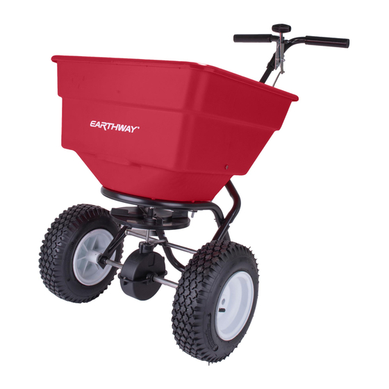
EarthWay 2170T Manuale di montaggio e istruzioni per l'uso - Pagina 2
Sfoglia online o scarica il pdf Manuale di montaggio e istruzioni per l'uso per Spreader EarthWay 2170T. EarthWay 2170T 6. Commercial tow
broadcast spreader
Anche per EarthWay 2170T: Manuale di montaggio e istruzioni per l'uso (6 pagine)

Impeller
Cross Brace
Gearbox Brace
DRIVE WHEEL
HOLE
Gearbox & Axle Assembly
3. Install impeller onto pinion shaft. Insert 1/8"x 1¼" cotter pin through
impeller then through pinion shaft. Use hole closest to the gear box. Spread
cotter pin to prevent from falling out. Next, insert the Cross Brace into the
Gearbox Brace.
Axle Bearing
Flat
Side
5. Install axle bearings to both lower
handles. NOTE: Notch on bearings and
lower handles. Bearings must go through
flat side of lower handle.
6. A - Install lower handles onto axle
to both sides as shown. Insert 2¼" bolt
through second hole in lower handle and
through first hole in frame install locknut.
DO NOT TIGHTEN.
B - Now insert 1½" bolt through first hole in lower handle. Then through frame brace. NOTE: Numbers on frame brace must be facing
toward gear box as shown. Next into threaded connector in cross brace. DO NOT TIGHTEN.
C - Next insert 1½" bolt through other end of frame brace and through second hole in frame install the second cross brace - this one has a
cross hole in the center of the tube.
PAGE 2
Pinion
Shaft
⅛ x 1¼"
Cotter Pin (#36105)
COAST WHEEL
HOLE
Notch
Drive wheel
side
1/4-20 x 1½"
Hex Head Bolt
Step 6B & 6C
1/4-20 x 2¼"
Hex Head Bolt
Step 6A
4. Install gear box by inserting the pinion shaft into hole in center of
hoppers bottom. The word "FRONT" on the gearbox must point to
Front of the hopper. Follow label instructions on hopper.
Gearbox &
Axle Assembly
Cross Brace
Impeller
Shut-Off
1/4-20 Locknut
Front
Coast wheel
side
Numbers
Frame brace
Frame
1/4-20 x 1½"
Pan Head Bolt
Lower Handle
Pivot Rod
