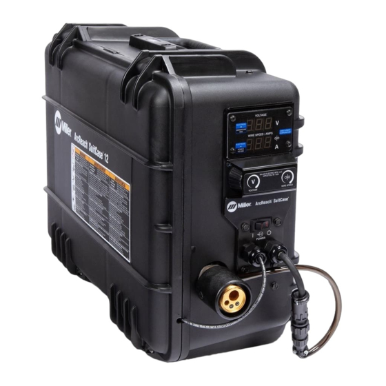
Miller ArcReach SuitCase Non-CE Manuale d'uso - Pagina 29
Sfoglia online o scarica il pdf Manuale d'uso per Sistema di saldatura Miller ArcReach SuitCase Non-CE. Miller ArcReach SuitCase Non-CE 48.

5-12. Motor Board (PC1) DIP Switch Settings
�
Complete Parts List is available at www.MillerWelds.com
1
2
RC111
3
Ref. 247678-B
1 Motor Control Board PC1
2 DIP Switch SW1
3 LED5
�
DIP switch SW1 is used to match the
performance of PC1 to the characteris-
tics of the motor used in the feeder.
Setting SW1 as shown will help insure
that PC1 and motor are matched for
optimal performance.
If protective coating is present, remove be-
fore setting DIP switch. It is not necessary to
reapply the protective coating.
Set switch positions 1 and 2 so the de-
pressed section of both tabs are toward 1
and 2 as labeled on the switch. As shown in
illustration.
When feeder is powered up, LED 5 on the
motor control board will blink four times. This
blinking indicates everything is working prop-
erly and the DIP switch is set correctly.
After LED 5 is done blinking, it will be either
red or green. Red indicates that the feeder is
connected with electrode positive. Green in-
dicates feeder is connected with electrode
negative.
OM-278792 Page 23
