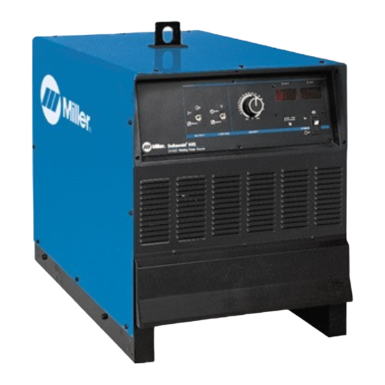
Miller Trailblazer 302 Diesel Manuale d'uso - Pagina 30
Sfoglia online o scarica il pdf Manuale d'uso per Inverter Miller Trailblazer 302 Diesel. Miller Trailblazer 302 Diesel 40. Generator power
Anche per Miller Trailblazer 302 Diesel: Manuale di applicazione (16 pagine)

6-1. Controls (Non CE Models)
1
Voltage Adjustment Control
Turn control clockwise to increase voltage.
Voltmeter value changes as control knob is
turned. Control can be adjusted while welding.
2
Digital Meters
Voltmeter displays preset voltage with contac-
tor off. Voltmeter and ammeter display actual
output voltage and amperage with contactor
on.
6-2. Controls (CE Models)
1
Voltage Adjustment Control
Turn control clockwise to increase voltage.
Voltmeter value changes as control knob is
turned. Control can be adjusted while welding.
2
Digital Meters
Voltmeter displays preset voltage with contac-
tor off. Voltmeter and ammeter display actual
output voltage and amperage with contactor
on.
OM-223 Page 24
.
A complete Parts List is available at www.MillerWelds.com
SECTION 6 − OPERATION
5
6
3
Power Switch With Indicator Light
4
High Temperature Shutdown Light
5
Remote Voltage Control Switch
For front panel control, place switch in Panel
position. For remote control, place switch in
Remote position, and connect remote device
(see Section 5-7).
6
Output Switch
6
5
3
Power Switch With Indicator Light
4
High Temperature Shutdown Light
5
Remote Voltage Control Switch
For front panel control, place switch in Panel
position. For remote control, place switch in
Remote position, and connect remote device
(see Section 5-7).
6
Output Switch
2
1
3
4
For front panel control of output, place switch
in Panel position. For remote control of output,
place switch in Remote position, and connect
remote device (see Section 5-7).
!
Weld output studs are energized only
when Output switch is in On position,
or while welding.
!
Turn Off power before connecting re-
mote device.
186 726-F
186 729-C
