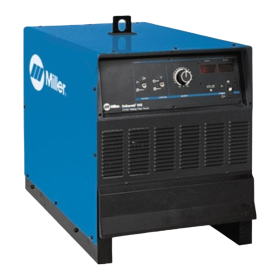
Miller Trailblazer 302 Diesel Kullanıcı El Kitabı - Sayfa 30
İnvertör Miller Trailblazer 302 Diesel için çevrimiçi göz atın veya pdf Kullanıcı El Kitabı indirin. Miller Trailblazer 302 Diesel 40 sayfaları. Generator power
Ayrıca Miller Trailblazer 302 Diesel için: Başvuru Kılavuzu (16 sayfalar)

6-1. Controls (Non CE Models)
1
Voltage Adjustment Control
Turn control clockwise to increase voltage.
Voltmeter value changes as control knob is
turned. Control can be adjusted while welding.
2
Digital Meters
Voltmeter displays preset voltage with contac-
tor off. Voltmeter and ammeter display actual
output voltage and amperage with contactor
on.
6-2. Controls (CE Models)
1
Voltage Adjustment Control
Turn control clockwise to increase voltage.
Voltmeter value changes as control knob is
turned. Control can be adjusted while welding.
2
Digital Meters
Voltmeter displays preset voltage with contac-
tor off. Voltmeter and ammeter display actual
output voltage and amperage with contactor
on.
OM-223 Page 24
.
A complete Parts List is available at www.MillerWelds.com
SECTION 6 − OPERATION
5
6
3
Power Switch With Indicator Light
4
High Temperature Shutdown Light
5
Remote Voltage Control Switch
For front panel control, place switch in Panel
position. For remote control, place switch in
Remote position, and connect remote device
(see Section 5-7).
6
Output Switch
6
5
3
Power Switch With Indicator Light
4
High Temperature Shutdown Light
5
Remote Voltage Control Switch
For front panel control, place switch in Panel
position. For remote control, place switch in
Remote position, and connect remote device
(see Section 5-7).
6
Output Switch
2
1
3
4
For front panel control of output, place switch
in Panel position. For remote control of output,
place switch in Remote position, and connect
remote device (see Section 5-7).
!
Weld output studs are energized only
when Output switch is in On position,
or while welding.
!
Turn Off power before connecting re-
mote device.
186 726-F
186 729-C
