CIOKS Adam link Manuale d'uso - Pagina 2
Sfoglia online o scarica il pdf Manuale d'uso per Alimentazione CIOKS Adam link. CIOKS Adam link 2. Power supply for effect pedals

Overview
Right side
On the right side of the enclosure you'll find the 4 outlets of the power supply as RCA sockets
which all are centre positive. Correct polarity for the pedal is achieved by using the right Flex
cable.
The red settings switch with two white knobs placed just to the right of the outlets should be
used to set the output voltage of outlets 3 and 4. The left knob is for setting of outlet 3, the
right one is for outlet 4.
Knob no. *
Function
1
Outlet 3
2
Outlet 4
* counting from left, opposite order of the white digits on the red switch (if you can see them)
Top
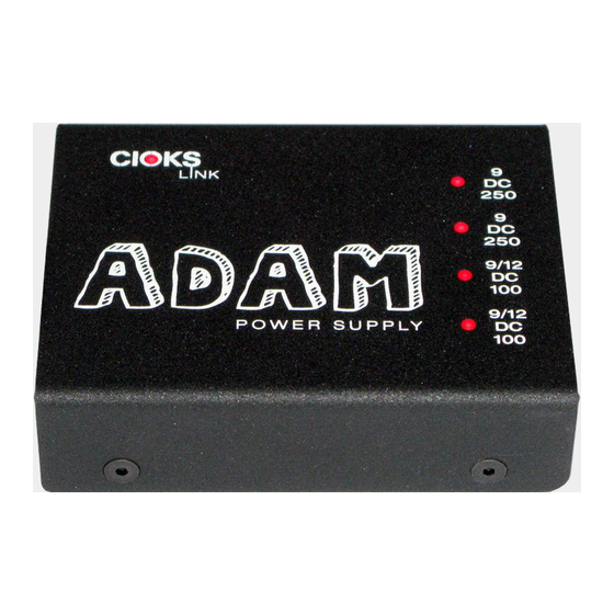
CIOKS logo has a red LED placed in the middle of the letter 'O'. When this LED is lit the
power supply is connected to mains and operates.
On top of the enclosure you see the output voltage and max. current rating of each outlet
printed just above the outlet sockets. The top figure is the voltage and the DC in the middle
line tells you it's a direct current outlet. Outlets with two possible voltage settings have both
values stated as 9/12. The bottom figures states the maximum current capability of each outlet
in mA.
The status of each isolated output is shown by a LED indicator also situated on top of the
enclosure just above the voltage figure. The function of this advanced and unique monitoring
feature is described in detail later on.
Left side
On the left side of the enclosure you'll find the AC power input connector, which is a C6 type
according to the IEC 60320 standard also used in many laptop adapters. On the same side as
the AC mains input you'll find the mains voltage selector switch and the fuse.
Mains voltage selector switch should be used for setting the correct mains voltage 115 or
230V. The Japanese version is made only for a 100V nominal mains voltage and has no mains
voltage selector switch.
The fuse is the only part which may be replaced by the user. In case it's blown, replace with a
5x20mm, T 200mA (slow blow/time lag) type.
Bottom
The four detachable rubber feet are situated on the bottom of the enclosure. On this same
surface you'll find 4 holes with metric M4 threads, which should be used for easy mounting of
Knob down
Knob up
9V DC
12V DC
9V DC
12V DC
the power supply to a pedalboard. Do not use screws, which would go further than 5mm inside
the unit. Have a look at the mounting guide on CIOKS web site.
Getting started
First make sure that the voltage value chosen on the voltage selector switch matches the mains
voltage in your wall socket. Connect the mains power cord to the power supply and mains.
Using the right Flex cable types connect your pedals to the outlets of power supply making
sure that the voltage and current is correct for every pedal.
Advanced LED Monitoring feature
Each isolated outlet has its individual LED status indicator. The indicator is fully lit in normal
operation of a particular outlet. Its light gets dim when you operate just on the edge of the
current limit. If you overload or short circuit an outlet, the respective LED indicator turns off.
The LED indicators of outlets 1, 2, 5 and 6 with selectable output voltages also show you the
voltage set by the settings switch. In case a higher voltage than the default 9V setting is
selected for a given outlet, its respective LED indicator will be lit with higher intensity than the
other indicators.
All indicators take into account the actual level of mains voltage when monitoring a possible
overload. The current limits for each outlet or section of the power supply are specified at
nominal level of the mains voltage. In Europe it's 230V, 120V in e.g. United States and 100V
in Japan. If the mains voltage is higher than nominal, you can draw more current from the
power supply than stated in the specifications. This would never be a problem. A more
common situation though, is when the mains voltage is lower than nominal. In such a case
maximum current ratings for each outlet or section might be diminished.
The advanced LED monitoring of each isolated outlet will alert you in case of an overload or
short circuit. If such a situation happens you know where to look to solve the problem.
A glance at the LED status indicators and you have proof of 100% clean power to your pedals.
Included accessories
Flex cables
CIOKS offers a great selection of different Flex cable types for connection your pedals to the
power supply. Below you see a list of the included Flex cables with your unit:
•
Type 1 – black with 5,5/2,1mm centre negative DC-plug
•
Type 5 – black with 3,5mm tip positive jack-plug
•
Type 1 – Split Flex (to power two pedals of one outlet)
x4
x1
x1
