ABB ScreenMaster RVG200 Istruzioni per la messa in servizio - Pagina 6
Sfoglia online o scarica il pdf Istruzioni per la messa in servizio per Strumenti di misura ABB ScreenMaster RVG200. ABB ScreenMaster RVG200 17. Paperless recorder terminal block failures
Anche per ABB ScreenMaster RVG200: Manuale (17 pagine), Procedura di sostituzione della batteria (4 pagine), Manuale (2 pagine), Istruzioni di servizio (2 pagine)
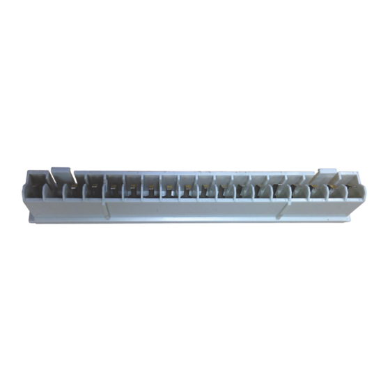
Accessing the recorder connection terminals
Referring to Fig. 3:
1. Press the terminal cover release plate in recess
B
pull terminal cover
expose the terminal connections.
Fig. 3 Accessing the recorder connection terminals
6
A
away from the recorder body to
Power supply connections
Referring to Fig. 4:
and
1. Make connections to the power supply terminals
(module position E) as follows:
–
AC supply: terminals 1 (line), 2 (neutral), 3 (ground)
or
–
DC supply: terminals 4 (+), 5 (–)
Note. Tighten terminal screws to a torque of
0.1 Nm (0.9 lbf.in).
A
Fuse 500 mA Type T IR = 100 A
Line
Neutral
Warning. Use fuse rating 500 mA (max.) Type T
2.5 A Type T
Warning. Use fuse rating 2.5 A (max.) Type T
Fig. 4 Power supply connections and fuse ratings
AC power supply
earth (ground)
stud
Module positions
B
C
D
E
1
2
3
4
5
1
L
2
N
3
(UL category JDYX2)
AC Supply
Fuse
3
24 V DC
4
+
–
5
DC Supply
Power
supply
terminals –
see below
100 to 240 V
50 / 60 Hz
CI/RVG200–EN