ABB ScreenMaster RVG200 Instruções de colocação em funcionamento - Página 6
Procurar online ou descarregar pdf Instruções de colocação em funcionamento para Instrumentos de medição ABB ScreenMaster RVG200. ABB ScreenMaster RVG200 17 páginas. Paperless recorder terminal block failures
Também para ABB ScreenMaster RVG200: Manual (17 páginas), Procedimento de substituição da bateria (4 páginas), Manual (2 páginas), Instrução de serviço (2 páginas)
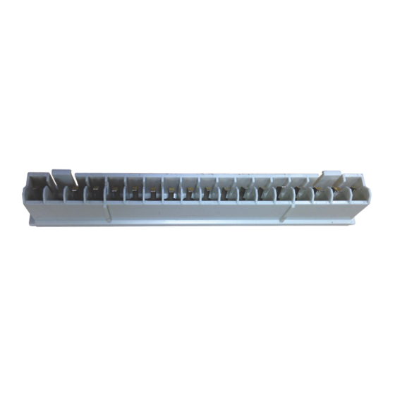
Accessing the recorder connection terminals
Referring to Fig. 3:
1. Press the terminal cover release plate in recess
B
pull terminal cover
expose the terminal connections.
Fig. 3 Accessing the recorder connection terminals
6
A
away from the recorder body to
Power supply connections
Referring to Fig. 4:
and
1. Make connections to the power supply terminals
(module position E) as follows:
–
AC supply: terminals 1 (line), 2 (neutral), 3 (ground)
or
–
DC supply: terminals 4 (+), 5 (–)
Note. Tighten terminal screws to a torque of
0.1 Nm (0.9 lbf.in).
A
Fuse 500 mA Type T IR = 100 A
Line
Neutral
Warning. Use fuse rating 500 mA (max.) Type T
2.5 A Type T
Warning. Use fuse rating 2.5 A (max.) Type T
Fig. 4 Power supply connections and fuse ratings
AC power supply
earth (ground)
stud
Module positions
B
C
D
E
1
2
3
4
5
1
L
2
N
3
(UL category JDYX2)
AC Supply
Fuse
3
24 V DC
4
+
–
5
DC Supply
Power
supply
terminals –
see below
100 to 240 V
50 / 60 Hz
CI/RVG200–EN