ABB ScreenMaster RVG200 Instruções de colocação em funcionamento - Página 7
Procurar online ou descarregar pdf Instruções de colocação em funcionamento para Instrumentos de medição ABB ScreenMaster RVG200. ABB ScreenMaster RVG200 17 páginas. Paperless recorder terminal block failures
Também para ABB ScreenMaster RVG200: Manual (17 páginas), Procedimento de substituição da bateria (4 páginas), Manual (2 páginas), Instrução de serviço (2 páginas)
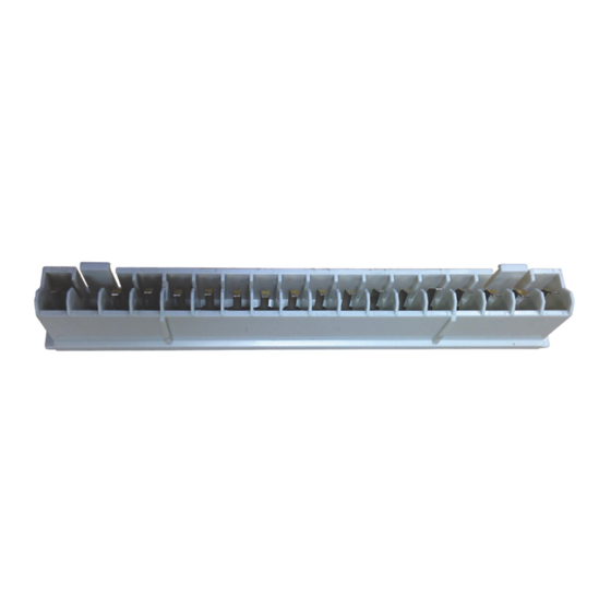
Analog input / relay / hybrid connections
Notes.
Tighten terminal screws to a torque of 0.1 Nm (0.9 lbf.in).
Analog inputs:
3-Lead RTD: 3-leads must have equal resistance, not exceeding 20 each
–
–
for mA input types, to ensure loop continuity when the recorder is switched off, fit a suitably-rated diode (for example,
type 1N4148 or equivalent)
Inputs 1 to 6
*
+
*Each thermocouple input must have either a cold junction assembly (part number CM30/0052) or shorting link (part number RVG200/0118) fitted.
Each analog input card with a thermocouple input must have a minimum of 1 cold junction assembly fitted.
Cold junction
Fig. 5 Analog input / relay / hybrid connections
Connecting a 2-lead temperature transmitter
24 V DC
+ +
Current limited
transmitter
to 22.8 mA
_
maximum
Using an external 24 V power supply
Fig. 6 Connecting a 2-wire temperature transmitter
CI/RVG200–EN
A, B, C, D
A, B, C, D
Analog Input
Relay
N/C
1
Input 1
N/O
2
C
3
N/C
4
Input 2
N/O
5
C
6
N/C
7
Input 3
N/O
8
C
9
N/C
10
Input 4
11
N/O
12
C
N/C
13
Input 5
14
N/O
15
C
N/C
16
Input 6
N/O
17
C
18
A, B, C, D
Analog input
2-wire
_
Input 1
C, D
Hybrid
1
1
1
2
2
3
3
4
2
4
5
5
6
3
6
7
7
8
4
8
9
9
10
5
10
11
11
12
6
12
13
1+
13
14
2+
14
15
15
3+
16
4+
16
17
5+
17
18
Common
18
Analog
1
input
2
+
3
Input 1
Using an internal Tx power supply or hybrid board
E
Power supply
L
1
100 to
240 V AC
N
2
3
+
4
24 V
DC
–
5
6
7
8
Tx
9
+
Tx
10
–
Tx / Rx
+
11
Tx / Rx
–
12
Communications
13
common
RJ45
USB
2-wire
_
+
transmitter
Analog or digital output 1
1
Tx PSU 1
2
3
Analog or digital output 2
Tx PSU 2
4
Hybrid
+
1
_
2
3
4
7