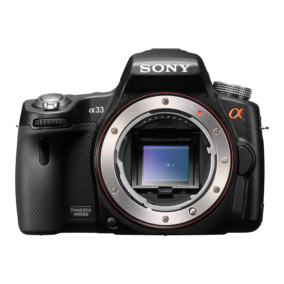
Sony SLT-A55V - alpha; Translucent Mirror Technology™ Dslr Manuale di servizio - Pagina 15
Sfoglia online o scarica il pdf Manuale di servizio per Fotocamera digitale Sony SLT-A55V - alpha; Translucent Mirror Technology™ Dslr. Sony SLT-A55V - alpha; Translucent Mirror Technology™ Dslr 30. Interchangeable lens digital camera/zoom lens kit
Anche per Sony SLT-A55V - alpha; Translucent Mirror Technology™ Dslr: Manuale delle funzioni (7 pagine), Specifiche tecniche (2 pagine)

2-1-3. LCD SECTION
103
(Note3)
101
Claw
102
Claw
Claw
#11
111
(Note2)
Claw
#2
Ref. No.
Part No.
Description
101
4-192-304-01
CV P CABINET (C)
* 102
4-192-305-01
CV LCD HINGE COVER (C)
103
1-880-883-11
LCD-021 FLEXIBLE BOARD (Note3)
104
X-2548-489-1
CV LCD HINGE ASSY
* 105
4-192-306-01
CV LCD HINGE COVER (M)
106
1-881-235-21
SHD-002 FLEXIBLE BOARD
107
A-1781-920-A
PD-414 BOARD, COMPLETE
* 108
1-471-558-11
MAGNET (NEO44) (Note1)
109
4-192-309-01
EM LCD BOARD TAPE
SLT-A33/A33L/A33Y/A55/A55V/A55L/A55VL/A55VY_L2
108
(Note1)
107
109
106
#2
105
104
Claw
Claw
A
110
Ref. No.
Part No.
Description
* 110
4-192-303-01
EM PD GROUND PLATE
* 111
1-471-559-11
MAGNET (NEO44) (Note2)
LCD901 A-1789-529-A
P CAB M BLOCK ASSY (SERVICE)
#2
2-635-562-31
SCREW (M1.7)
#11
3-078-890-11
SCREW, TAPPING
Screw
#2: M1.7 X 4.0
(Black)
2-635-562-31
1.7
4.0
Note
LCD901
Note1: Put the marking side in the position as shown in the figure
when you install the magnet.
A
Note2: Put the marking side in the position as shown in the figure
when you install the magnet.
Marking
Note3: Refer to "Assembly-1: Method of attachment of LCD-021
Flexible Board" when you assemble.
2-5
#11: M1.7 X 4.0 (Tapping)
(Silver)
3-078-890-11
1.7
4.0
Note1: マグネットを取付ける際は,マ-キング面を図の位置にあわ
せてください。
Marking
Note2: マグネットを取付ける際は,マ-キング面を図の位置にあわ
せてください。
Note3: 組立時は "Assembly-1: Method of attachment of LCD-021
Flexible Board" を参照してください。
