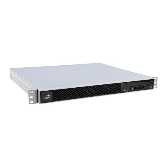
Cisco Firepower Threat Defense for the ASA 5506-X Series Using Firepower Device Manager Quick Start Guide
● IPv4 Address—Select Static for the address type, then enter an address and subnet mask. For example,
192.168.10.1/24.
d.
Click Save.
2.
Add the Wi-Fi interface to the same security zone as the inside interface.
During device setup, you configured the inside interface and placed it in a security zone named inside_zone.
The Wi-Fi interface needs to be in the same zone so that you can reach the access point web interface.
a.
Click Objects in the menu, then select Security Zones from the table of contents.
b.
Click the edit icon
c.
Click + under Interfaces and select the wifi interface.
3.
Configure an access control rule to allow traffic between interfaces in the inside_zone security zone.
The device setup wizard creates a rule to allow traffic to flow from the inside_zone to the outside_zone,
which allows inside users to get to the Internet. By adding the wifi interface to inside_zone, Wi-Fi users are
also included in the rule that allows Internet access.
However, the default action is to block all traffic, so you must create a rule to enable traffic between the
interfaces in the inside_zone security zone.
a.
Click Policies in the menu.
b.
Click + above the Access Control table to add a rule.
c.
Configure at least the following options in the rule.
● Title—Enter a name for the rule. For example, Inside_Inside.
● Action—Either Allow or Trust.
● Source/Destination > Source Zones—Select inside_zone.
● Source/Destination > Destination Zones—Select inside_zone.
d.
Click OK.
4.
Configure the DHCP server on the wireless interface.
The DHCP server supplies IP addresses to devices that connect to the access point. It also supplies an
address to the access point itself.
a.
Click the device name in the menu to get to the Device Dashboard.
b.
Click System Settings > DHCP Server.
c.
Click + above the DHCP server table.
d.
Configure the following DHCP server properties.
● Enable DHCP Server—Click the slider to enable the DHCP server.
● Interface—Select the wifi interface.
● Address Pool—Enter the address pool for DHCP clients. For example, if you used the example address
for the wireless interface, the pool would be 192.168.10.2-192.168.10.254. The pool must be on the same
subnet as the IP address for the interface, and it cannot include the address of the interface or the
broadcast address.
e.
Click Add.
5.
Click the Deploy button in the menu, then click the Deploy Now button
device.
(
) for inside_zone.
7. Configure the Wireless Access Point (ASA 5506W-X)
(
) , to deploy your changes to the
10

