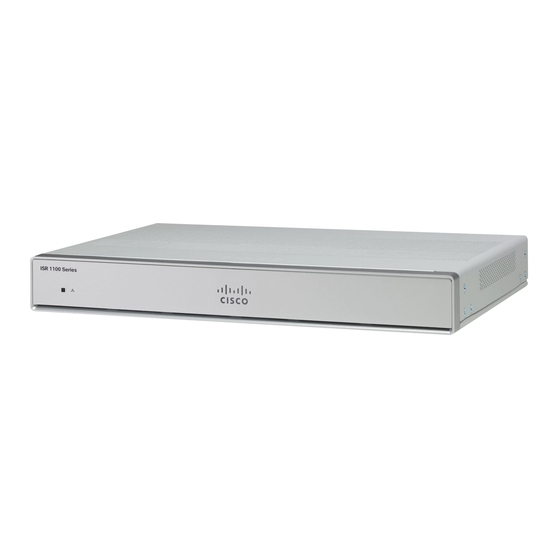
Cisco C1101-4P Installazione e connessione - Pagina 8
Sfoglia online o scarica il pdf Installazione e connessione per Hardware di rete Cisco C1101-4P. Cisco C1101-4P 27. Install and upgrade internal modules and field replaceable units
Anche per Cisco C1101-4P: Manuale (12 pagine)

Wall Mount the Router
Wall Mount the Router
Depending on the models of the Cisco 1100 Series Integrated Services Routers (ISRs), the tasks for mounting
the router chassis on the wall may vary.
Warning
Read the wall-mounting instructions carefully before beginning installation. Failure to use the correct hardware
or to follow the correct procedures could result in a hazardous situation to people and damage to the system.
Statement 378.
Note
The recommended clearance when a router is horizontally mounted is 1.5 inches on both sides for clearance
and 1.75 inches on top. I/O side clearance is needed as it is required to access the cable connections. Clearance
is not required on the backside (opposite side from I/O face) unless mounting on a DIN Rail. Clearance is
required to attach and mount the DIN rail bracket.
There are two ways to mount a router on the wall, using Key-hole Slots and DIN Rail Brackets.
Wall Mount Using Key-hole Slots
The Cisco 1100 Series Integrated Services Routers (ISRs) have key-hole slots at the bottom of the chassis for
mounting on a wall or any vertical surface.
Note
Do not mount the router with the output ports facing downwards. For the C111x series, ensure that the cables
are placed on the sides.
Note
When choosing a location for wall mounting the router, consider cable limitations and wall structure.
Note
To attach a router to the wall stud, each bracket should have one number10 wood screw (pan-head) with
number10 washers, or two number10 washer-head screws. The screws must be long enough to penetrate at
least 1.5 inches (38.1 mm) into the supporting wood or metal wall stud.
Note
For hollow-wall mounting, each bracket requires two wall anchors with washers. Wall anchors and washers
must be size number 6 (pan-head). Route the cables so that they do not put a strain on the connectors or
mounting hardware.
Install and Connect the Router
8
Install and Connect the Router
