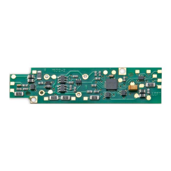
Digitrax DN166I2B Foglio di istruzioni - Pagina 3
Sfoglia online o scarica il pdf Foglio di istruzioni per Giocattolo Digitrax DN166I2B. Digitrax DN166I2B 8.

Installation Notes
1.
Do not exceed the decoder's
500mA total function output
rating.
2.
We recommend that the Blue
wire, also called +Common or
Lamp Common, be connected
as shown. If you wish to omit
the Blue wire in your instal-
lation, consult the Digitrax
Decoder Manual for more
information.
3.
The head lamp should
be hooked up using the
Blue/+Common wire for
optimal Digitrax transponding
operation.
4.
To use a function output with
an inductive (coil) type load, see
the Digitrax Decoder Manual
for more information to avoid
damage to the decoder.
5.
See the Digitrax Decoder Man-
ual for full details of wiring 12-16V lamps, 1.5V lamps, and LEDs. Lamps that
draw more than 80 mA when running require a 22 ohm 1/4 watt resistor in
series with the directional light function lead to protect the decoder.
6.
Some locomotives employ filter capacitors for RFI suppression in the loco-
motive wiring. These may cause problems with Supersonic decoders and
non-decoder analog operation on DCC. This capacitor should be removed for
safe operation.
Customizing Your Decoder
Your Digitrax decoder is ready to run and will operate using address 03 with no
additional programming. For a more prototypical railroading experience, your
decoder can be customized for your specific locomotive by programming some of
the Configuration Variables, or CVs, available. See the Digitrax Decoder Manual
or the Digitrax web site for more information.
© 2014 Digitrax, Inc.
Figure 3: Wires unsoldered from
light board.
Figure 4: Wires soldered onto
the DN166I2B
— 3 —
Wires soldered on.
www.digitrax.com
