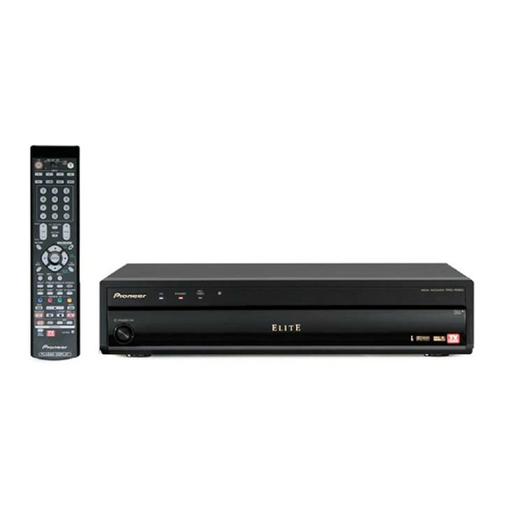
Pioneer Elite PRO-R06U Manuale di formazione - Pagina 39
Sfoglia online o scarica il pdf Manuale di formazione per Ricevitore Pioneer Elite PRO-R06U. Pioneer Elite PRO-R06U 47. Pioneer 6th generation plasma media receivers

6G MR (Tips for removing the Main PCB)
Use the chart below to remove each PCB.
Front Panel
LED board
Front input board
PC card board
Note:
Remove the 2 parts, shown by red circles, before removing Front Panel Assy.
( The reason is that FCC will be pulled when removing Front Panel Assy. )
Remove FCC
In case of placing Power Supply, Digital Tuner and AV PCB, make sure to attach the screw on the Connector Panel side first.
( The reason is to prevent the stress to PCB and solder. )
Please pay attention the styling and binding of cord around Power Supply.
After replacing the parts, stabilize the FAN (60X25L) with tape as shown before removing in order to prevent a loose FAN while shipping.
Note: Please pay attention for not breaking screw. The screw for HDMI and I-Link are weak and tend to be broken.
Bonnet
Fan motor
DTB
Fan motor
Power Supply
Main board
Remove Flat Clamp
Make a note of the wire locations.
Make sure to clamp the cords under the
Cable Clamp.
Fan connectors need to be connected as pictured.
For FAN (60 X25L)
For FAN (40 X 10.5L)
Use asetate tape, approx 10mm wide.
39
