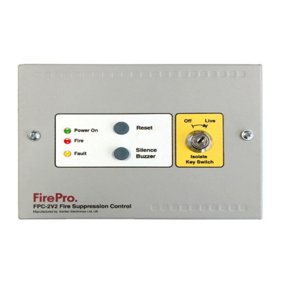
FirePro FPC-2 Manuale di funzionamento e manutenzione - Pagina 3
Sfoglia online o scarica il pdf Manuale di funzionamento e manutenzione per Controllore FirePro FPC-2. FirePro FPC-2 7. Fire control panel system isolation
Anche per FirePro FPC-2: Manuale di funzionamento e installazione (14 pagine), Manuale di funzionamento e manutenzione (8 pagine), Manuale di avvio rapido (2 pagine)

Note: The controller will continue to show a fault condition until the Aerosol Generators are replaced.
3. Installation and Mounting
This equipment is designed to be operated from 24V DC supply. This power supply must be battery backed.
The FPC-2 should be effectively bonded to earth. Failure to ensure that all conductive accessible parts of this
equipment are adequately bonded to earth will render the
equipment unsafe.
This control panel is designed for indoor use only and at
temperatures between -5
maximum relative humidity of 95%. Panels is rated to IP30 and
suitable for mounting indoors.
Operation outside of these limits may render the equipment unsafe.
MOUNTING - The control panel should be mounted on a dry, flat
surface, in a level position such that the enclosure is not distorted.
Suitable fixings of a minimum of 4mm diameter are to be used at
all fixing points such that the control panel is securely mounted.
The panel should not be mounted in another enclosure or near
sources of excessive heat.
Cables should be connected using cable glands fitted to the
knockouts. If additional entry points are required, all swarf and
debris caused by drilling of additional cable entries must be cleared
before power is applied to the panel.
Mains supply
Mains supply fuse
Operating Voltage
Output voltage
Standby Current
Extinguishant release output
Low Voltage limit
Extinguishant release
Extinguishant release duration
Detection Type
Detection Circuit End of Line
Fault relay contact rating
Fire relay contact rating
Cabling
Cable Entries
Terminal capacity
Construction
Connecting to the circuit board
All connections for field wiring are
to a single row of terminals along
the top of the circuit board.
Cabling must comply with the
Australian
Standards.
resistance of any cable must not
exceed 25 ohms.
Terminals are capable of accepting
wires of up to 2.5mm
2
.
Power 24v IN – 24v OUT
The polarity of these terminals is very important. The 24V IN is for connection of the power from a previous unit
or a power supply and the 24V OUT is for connection to further units.
fp_c2_m5.3
0
C (+/- 3) and +40
0
C (+/-2) and with a
Specifications
24V DC +10% - 15%
1.6Amp (Quick Blow)
19-30V DC
19-30V DC +/- 2%
18mA
18 to 30V DC. Fused at 1.6 Amp
6V DC – at this point unit is operational will send fault signal to Sigma XT Panel
Immediate – Max 4 FirePro Aerosol units
Latched - Continuous
Latching Type NO – LHD Cable Max
6K8 5% ½ Watt resistor
30VDC 1A Amp max
30VDC 1A Amp max
FP200 or equivalent (maximum capacitance 1uF maximum inductance 1 millihenry)
6 x20mm knockouts provided
0.5mm
2
to 2.5mm
1.2mm steel – Epoxy Powder Coated
The
DIMENSIONS - 135H x 189W x 50D mm
2
solid or stranded wire
Page 3 of 7
