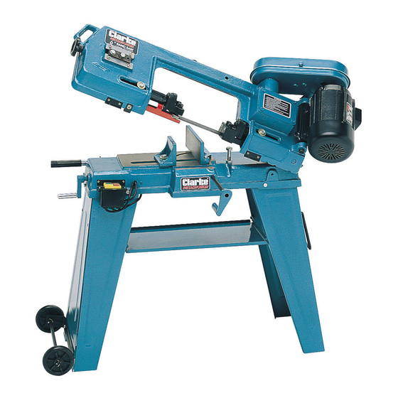
Clarke Metalworker CBS45MD Manuale d'uso e manutenzione - Pagina 9
Sfoglia online o scarica il pdf Manuale d'uso e manutenzione per Sega Clarke Metalworker CBS45MD. Clarke Metalworker CBS45MD 19. 6” (152mm) bandsaw

before mounting the pulley cover. Having done so, lower the Pulley Cover
over the shafts, ensuring the elongated hole is over the motor shaft.
Replace the screw removed earlier through the pulley cover, into its hole
in the circular plate. (This screw now locates and secures the pulley cover
at the gearbox shaft).
The only other mounting is beneath the pulley cover. Fit the mounting bolt
supplied.
For safety purposes, a micro switch is provided which will automatically cut
off the electrical supply, thereby preventing the machine from operating
when the pulley cover lid is opened. The micro switch is mounted on the
inside of the pulley cover, between the two pulleys. Electrical connection
now needs to be made. To do this, it is first of all necessary to remove the
micro switch from its mounting by unscrewing the two mounting screws.
A cable, from which extends two wires fitted with push on connectors, is
clipped to the main body beneath the pulley cover (on The motor side).
The wires should be threaded through the hole and grommet provided in
the pulley cover, beneath the micro switch mounting (item 4).
The micro switch carries three terminals (See
Fig 2). One of the wires should be connected
to the terminal marked "COM" or "C", whilst
Microswitch
the other should be connected to the
terminal marked "NO". Once the terminals
are connected, the micro switch can be
remounted using the two mounting screws
Fig. 2
provided.
Check to ensure the micro switch plunger operates correctly, and do not
over tighten the mounting screws.
The micro switch plunger is operated by an actuating tab, attached to the
pulley cover lid, so that when the lid is closed the plunger is forced IN
thereby closing the circuit and allowing the machine to operate.
It is IMPORTANT to ensure that the actuating tab meets the plunger
cleanly. Raise and lower the lid and make certain you can hear the
microswitch operate. It may necessary to bend the actuating tab slightly
to ensure correct operation.
The pulleys may now be fitted. Note that they are not interchangeable.
The motor shaft pulley is located with a key and grubscrew, and a keyway
is therefore provided in the bore, whilst the gearbox pulley has no keyway,
and is located with a grubscrew, on a flat milled on the shaft.
IMPORTANT. When fitting, ensure that the smallest diameter motor or drive
pulley is driving the largest diameter gearbox or blade pulley, i.e. they are
mounted in reverse to each other. It is normal to assemble the drive pulley
9
