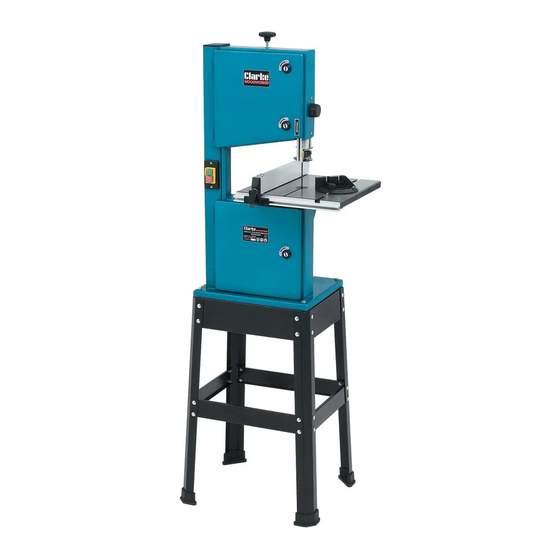
Clarke WOODWORKER CBS250 Manuale di istruzioni per l'uso e la manutenzione - Pagina 9
Sfoglia online o scarica il pdf Manuale di istruzioni per l'uso e la manutenzione per Sega Clarke WOODWORKER CBS250. Clarke WOODWORKER CBS250 13. 45 mm (10”) bandsaw & stand
Anche per Clarke WOODWORKER CBS250: Istruzioni per il funzionamento e la manutenzione (20 pagine)

Parts Diagram
IMPORT ANT:
he use of parts other than CLARKE replacement parts may result in safety hazards,
T
decreased tool performance and may invalidate your warranty.
-14-
ASSEMBLY
Stand
Assemble sub assy x 2, see fig. 3.
1.
Parts required per assy, 2 legs (L), 1 short beam (H), 1 short
cross member (D), and 8 short round head screws nuts and
washers.
Do not fully tighten until all screws and nuts are loosely
fitted, once all screws are fitted, check assy for squareness
and tighten nuts, do not overtighten.
NOTE: beams and cross members fit inside legs, screws are fitted
from the outside with washers and nuts on the inside.
Connect sub assys together using 2 long cross members
2.
(E), 2 long beams (G), and 8 short round head screws nuts
and washers, 8 short hex head bolts washers and nuts, DO
NOT tighten until all screws etc are loosely fitted.
NOTE: long beams are fitted on top of short beams see Fig .4
For details. Hex head bolts are fitted from the top with washers
and nuts on the underside.
urn assembly upside down and fit one rubber foot to
3.
T
each leg, by simply pushing on.
Turn stand over onto its feet, ensure all screws, nuts
and bolts are fully tightened, stand is secure and does
not rock about.
If stand does rock, loosen screws, nuts and bolts slightly,
seat stand firmly and retighten all screws etc.
With assistance, carefully lift the machine onto the stand, line up corner holes for
4.
securing, secure machine to stand using, 4 long hex head bolts, fitted from the top
with washers and nuts on the underside, fit all four bolts before final tightening, do
not overtighten.
5.
Fit the table (M), onto trunnion, secure using
A
four Hexagonal bolts (
) and shakeproof
washers see Fig. 5, do not overtighten.
Before switching ON, adjust the table so that
the saw blade runs through the centre of the
tables insert slot.
Centering The Table
B
Loosen the four screws (
) securing the trunnion to
the machine frame.
Adjust the table so that the saw blade runs
through the centre of the table insert.
T
ighten the securing screws, and check saw blade still runs in the centre of the
table insert, if not carry out the adjustment again.
Fig. 3
Fig. 4
A
Trunnion
Fig. 5
-7-
B
