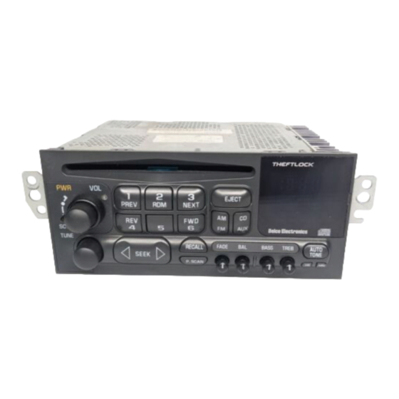
Discount Car Stereo BLU-C5 Manuale di istruzioni per l'installazione - Pagina 5
Sfoglia online o scarica il pdf Manuale di istruzioni per l'installazione per Ricevitore Discount Car Stereo BLU-C5. Discount Car Stereo BLU-C5 12. Music streaming module for seelect 1997-04 corvette
Anche per Discount Car Stereo BLU-C5: Manuale di installazione (9 pagine), Istruzioni per l'installazione (12 pagine), Manuale di installazione (10 pagine), Manuale di installazione (8 pagine), Manuale di installazione (12 pagine)

10-pin connector
3. Tap installation harness red wire to 12V accessory supply in vehicle
Where to get 12V Accessory supply:
1997-03 vehicles have a 3-pin plug under passenger toe board near BCM (may
be covered in black duct tape) -- See Fig. 9
The yellow wire is ACC.
If vehicle does not have 3-pin plug; go to Alternate 12V
Acc. supply below.
Note: 3-pin plug may not be present in all vehicles and may have been
omitted from model year 2004.
Fig. 8
Fig.
Alternate 12V Acc. supply:
We recommend taping fuse #22 or #11 of interior fuse box
located under passenger seat behind toe board (See Fig. 11).
circuit seen in Fig. 10 may be use for this purpose.
The add-a-fuse
mini-tap
fuse tap circuit
How to use the Add-a-fuse circuit connection
3. Strip 1/4- 3/8" insolation from included accessory wire.
4. Look inside blue connector to see where metal ends. Useful in step d.
5. Insert stripped wire to blue connector (See Fig. 10)
6. Hold wire in place and crimp down (crimping too, plyers etc.) After
crimp, pull wire to verify crimp integrity.
7. Remove fuse #22 or #11 (if present) from vehicle fuse box otherwise
skip to step g.
8. Insert factory fuse to empty slot on add-a fuse circuit
9. Insert add-a-fuse circuit to fuse slot #22 or# 11
Noteworthy: If fuse #22 or #11 is missing from fuse box, the empty fuse slot on
add-a-fuse tap remains empty. To test, turn ignition "ON" and verify LED inside
module is flashing, otherwise check voltage at fuse slot and/or check crimp
integrity,
Fig. 10
