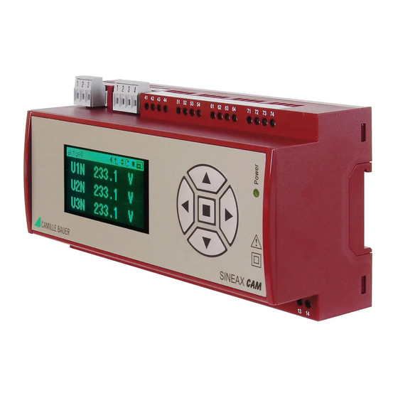
Camille Bauer SINEAX CAM Manuale di istruzioni per l'uso - Pagina 11
Sfoglia online o scarica il pdf Manuale di istruzioni per l'uso per Strumenti di misura Camille Bauer SINEAX CAM. Camille Bauer SINEAX CAM 12. Graphic display for sineax cam
Anche per Camille Bauer SINEAX CAM: Manuale di istruzioni per l'uso (19 pagine)

Internal clock (RTC)
Function:
Time reference, Counter for opera-
ting hours
Accuracy:
± 2 Minutes/Month (15 till 30°C)
trimmable via PC-Software
Synchronization via:
Measurement input,
HV-Input 110/230 V AC,
Synchronization pulse (digital in-
put)
Running reserve:
> 10 years
Response time
The total response time is the addition of the measurement
time t
of the input quantities and the processing time t
1
the respective output (analog output, bus, digital output,
relay).
Meas. time t 1
Processing time t 2
Input quantities
Analog output
Modbus, USB
Limit
monitoring
Measurement time t
1
Basic measurement quantities
Measurement interval:
programmable, 1 .. 999 periods
(Averaging time RMS value)
Measurement time t
:
2 x measurement interval
1
+ 17ms
System analysis quantities
Measurement interval:
18 periods
Measurement time t
:
2 x measurement interval
1
Analog input
Measurement time t
:
25 ms .. 30 s (programmable)
1
Digital input
Measurement time t
:
< 25 ms
1
HV-Input 110/230 V AC
Measurement time t
2 till 255 periods (programmable)
1
Total response time t
+ t
1
Analog output:
t1 + 10 ms .. 60 s,
programmable
Modbus / USB:
t1
Digital output:
t1 + 8 ms + Logic module
Relay:
t1 + 30 ms + Logic module
(Logic module: Switch-in/dropout delay 0...65 s, program-
mable)
Example: Relay has to toggle if P > P
50 Hz, Averaging time is 1 period, switch-in delay
logic set to 0 s
Logic
Digital
module
output
Relay
2
, rated frequency is
limit
Response time 40ms + 17ms + 0ms + 30ms = 87ms
Ambient conditions, general information
Operating temperature: – 10 till 15 till 30 till 55 °C
Storage temperature:
Relative humidity:
Variations due to
ambient temperature:
Long term drift:
Altitude:
Others:
for
2
Mechanical attributes
Dimensions:
t
Mounting:
Orientation:
Housing material:
Flammability class:
Weight:
Security
The current inputs are galvanically isolated from each
other.
Protection class:
Pollution degree:
Enclosure protection:
Measurement category: CAT III (at ≤ 300 V versus earth)
Rated voltage
(versus earth):
7.5 Logger and lists (optional)
By means of these options measurements and events may be
long-term recorded. Depending on the application 7 different
kinds of data may be acquisited:
– Progression of mean-values with interval time t1
(1s...60min)
– Progression of mean-values with interval time t2
(1s ... 60min)
– Min/Max values during interval t3 (1s ... 3h)
– Meter readings
– List entries of alarms
– List entries of events
– List entries of system messages
They share the available storage space of 64Mb size. The
memory allocation may be performed using the CB-Manager
– 25 till + 70 °C
< 95% no condensation
0.5x Basic accuracy per 10 K
0.2x Basic accuracy per year
≤ 2000 m max.
Usage group II
acc. IEC / EN 60 688
186 x 90 x 62 mm
On top-hat rail acc.
DIN EN 50 022 (35 x 15 mm and
35 x 7.5 mm)
Any
Polycarbonat (Makrolon)
V-0 acc. UL 94, self-extinguishing,
non-dripping, free of halogen
500 g
II (protective insulation, voltage
inputs via protective impedance)
2
IP 40, housing
(test wire, IEC/EN 60 529
IP 20, terminals
(test fi nger, IEC/EN 60 529)
CAT II (at > 300 V versus earth)
Power supply: 265 V AC
Relay:
250 V AC
I/O's:
30 V DC
264 V AC(HV-Input)
11
