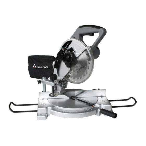
Altocraft 240-2087 Manuale dell'operatore - Pagina 6
Sfoglia online o scarica il pdf Manuale dell'operatore per Sega Altocraft 240-2087. Altocraft 240-2087 10. 8-1/4 inch compound miter saw

OPERATING PROCEDURES
5. To begin cutting, lower the cutting head. The movable guard opens automati-
cally.
6. After cutting, allow the head to come back up. The guard will close automati-
cally.
7. The saw will stop when you release the trigger switch.
MODES OF USE
Chop cut:
The head is locked in the upright position. The table rotation is locked at 0°.
This is a good setting for simple 90° crosscuts.
Miter cut:
The head is locked in the upright position. To unlock the table rotation, unscrew the
locking handle and press on the miter detent spring lever
with your thumb Move the table rotation to the left or right up to 45° left & 52° right.
The miter detent spring lever , if released, will stop the table at detents
at 0°, 15°, 22.5°, 30°, & 45° left and right. Use the locking handle to
lock the table at the desired angle, especially those in between the detents.
Bevel cut:
To unlock the head angle (bevel) adjustment, loosen the bevel lock handle
at rear of the saw. Lock it when the blade is tilted at the desired angle.
The table rotation is locked at 0°.
Compound cut:
Unlock and move the table rotation to the left or right as in miter cuts above. Using
the lever at the back of the saw, unlock the head and bevel it to any position from
0° – 45° left, then lock it in place.
NOTE: At extreme positions, the hold-down clamp should be moved to the right
side of the table to prevent interfering with the movement of the cutting head.
Always check before making the cut if there is any potential interference from the
clamp or any other part of the machine.
MAINTENANCE
NOTE:
E
ven though the angles are marked on the machine, it is always a good
idea to check them by making a trial cut. See Aligning Miter and Bevel, be-
low.
Inspect the cord regularly and have it replaced by an authorized repair facility if
it is damaged.
Check the brushes occasionally (after about 50 hours of use) and replace if
worn. The brushes can be replaced by removing the motor cap.
The brushes and their springs could jump out of the holders- be careful
not to lose them. Inspect the brushes. If the contact surface is not
smooth, or it is worn or heavily used, replace both brushes. Insert the new
brushes and springs in their holders and re-fasten the cap.
The plastic kerf plate table insert should be replaced if damaged to reduce the
risk of chips lodging in the slot and catching in the blade.
Keep the vents clear of dust and debris. This will help prevent possible electri-
cal shorts and ensure proper cooling.
Keep the tool housing and handle clean and free of oil and grease by using mild
soap and a damp (not wet) cloth.
6
