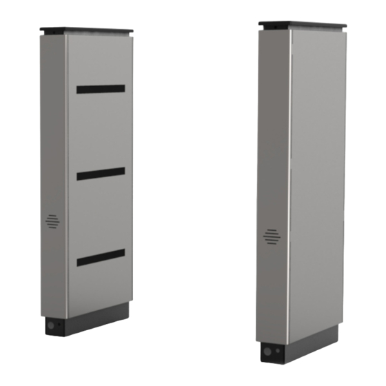
Alvarado Supervisor 500 Manuale di istruzioni per l'installazione - Pagina 9
Sfoglia online o scarica il pdf Manuale di istruzioni per l'installazione per Tornelli Alvarado Supervisor 500. Alvarado Supervisor 500 19. Barrier-free optical counting turnstile

Anchoring the Turnstile (cont.)
3.
Use a pencil and mark each anchor hole location
[Figure 15]. There will be a total of two (2) anchor
holes per cabinet. Remove the cabinets when
complete.
4.
Using a 1" concrete drill bit, drill the anchor holes a
minimum of 3" in depth at the center of each marked
location.
NOTE
The anchor holes must be clean before installing the
anchor bolts. If the holes are not clear of debris, the
anchor bolts may not tighten correctly.
5.
Insert the anchors into each drilled hole [Figure 16].
The threaded end of the anchor must be inserted into
the hole first. Use a rubber mallet to tap the anchors
into place, if needed. Ensure that the anchors are
flush with the concrete floor.
6.
If not already done, pull all wires (AC power, Ethernet
and crossover cable) through conduit and conduit
access holes prior to anchoring cabinets.
7.
Using clear RTV silicone, seal the gaps between the
conduit and conduit holes.
8.
Maneuver each cabinet over the anchor locations.
Insert two (2) 5/8" anchor bolts and flat washers.
9.
Using a torque wrench (ft-lb) and 15/16" socket,
torque the anchor bolts to 60 ft-lbs.
Page 16
For Assistance: [email protected] +1 (909) 591-8431
SU500 Installation Instructions
Figure 15
Marking Anchor Holes
Anchor
Holes
Figure 16
Anchoring
Concrete Anchor
PUD1456R5-0
SU500 Installation Instructions
Wiring Instructions
Primary Power
IMPORTANT
110VAC or 220VAC primary power (unless ordered otherwise)
must be hard wired in place. It is strongly recommended that a
licensed electrician perform this procedure in accordance with
all applicable local codes.
The primary power wiring lines for 110VAC and 220VAC consist
of the following:
Terminal
110V
220V
G
Green
Green/Yellow
round
N
White
Blue
eutral
L
Black
Brown
ine
1.
Locate the pre-installed power terminal block and attached
wiring (located on the master cabinet base) [Figure 17].
2.
Attach each primary power wire to the power terminal block
with the corresponding color exiting on the other side
[Figure 17A].
3.
Using a Phillips-head screwdriver, tighten each terminal
block connection.
NOTES
The orientation of the pre-installed terminal block may differ
from what is shown in [Figure 17 & 17A]. On some installations,
the terminal block is rotated 90 degrees.
Crossover Cable
The included crossover cable interconnects communication signals
and low-voltage power between the master and slave cabinets.
The default length of the crossover cable included with the SU500
is 11'. Optional crossover cable lengths of 20' and 40' are available.
1.
Connect one end of the crossover cable to the connector
tucked into the master cabinet as shown in [Figure 17].
2.
Connect the other end of the crossover cable to the transmitter
sensor array in the slave cabinet as shown in [Figure 18].
PUD1R5-0
For Assistance: [email protected] +1 (909) 591-8431
Primary Power and Crossover Cable
Figure 17
(Master Cabinet)
Crossover Cable
Connector
Fuse
Crossover Cable
Figure 17A
220VDC Shown
Crossover Cable Connection
Figure 18
(Slave Cabinet)
Status Light
Board
Crossover
Cable
Crossover Cable
Page 17
