Fleet Management MLT-400i Manuale di installazione - Pagina 5
Sfoglia online o scarica il pdf Manuale di installazione per GPS Fleet Management MLT-400i. Fleet Management MLT-400i 14.
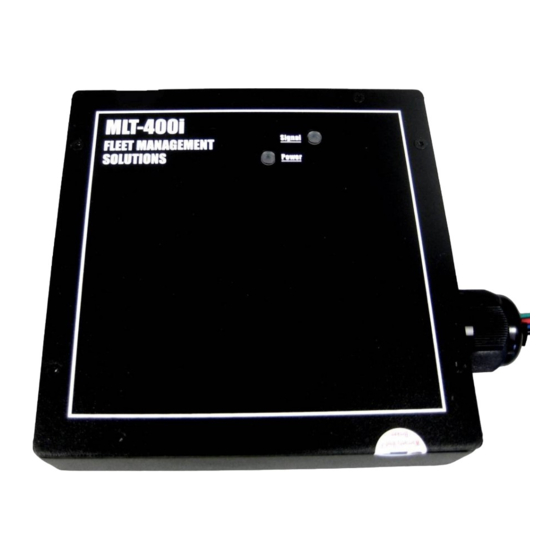
MLT-400i Installation Guide
2
Install Antenna
The MLT-400i antennas combine GPS and Iridium satellite antennas. The ANTIR01 is a
permanent mount (see Appendix A for additional information); ANTIR02 is a suction cup
window mount antenna. Proper installation is critical to achieve optimum performance.
Safety Considerations
• Some locations do not allow suction
mount antennas on the windshield.
Check your local regulations
Determine the Best Location
• Locate the antenna for an unob-
structed view of the sky, avoid
windscreens, ladder racks and other
radio antennas (minimum radius of 2
feet is recommended)
• Orient the antenna horizontally
• Ensure that the antenna GPS cable
connects to the MLT-400i GPS cable
and the Iridium cable connects to the
For customers wanting to create a visual tamper deterrent for the OBDII connector, Torque
Seal may be used to create a visual seal. FMS does not endorse or warranty Torque Seal.
• Apply Torque Seal "across"
desired connectors such as the
OBDII and antenna
• Torque Seal may be pur-
chased through Organic
Product Company
(http://www.opcompany.com)
• Do Not apply Torque Seal in-
side any connector so as to
interfere with electrical
continuity
11/18/2009
Tamper Deterrent – Torque Seal
FMS MLT-400i Installation Guide 4.3
MLT-400i Iridium cable (they are
color coded blue and black respec-
tively)
• Apply inspection torque seal if
desired (see below)
• Check antenna cable length will
reach to desired location; antennas
typically include 12 feet of cable
• Coil and secure any loose or extra
lengths of antenna cable, do not
allow cables to kink
• The antenna must be attached to the
MLT-400i prior to attaching power
Install Antenna
5