Fleet Management MLT-400i Manuale di installazione - Pagina 7
Sfoglia online o scarica il pdf Manuale di installazione per GPS Fleet Management MLT-400i. Fleet Management MLT-400i 14.
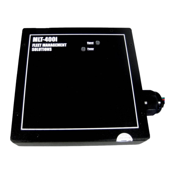
MLT-400i Installation Guide
• Ensure that connections are mechanically sound and properly insulated
• Use high quality electrical tape or shrink tubing, cheap tape will unravel in hot weather,
making it a poor insulator
• Never use "t-tap" connectors (poor quality mechanical type connection). Never "twist
and tape" without soldering your connection
Black Wire – Ground
• Connect to a ground wire in a harness or
• Connect to a bolt in the vehicle chassis
Red Wire – Continuous Power
• Attach the Red wire to the battery power or
• Connect, with the key Off, to a constant power of 9 to 24 volts DC. Use a voltmeter
and ensure that the voltage does not drop below 9 volts when starting the vehicle.
Green Wire – True Ignition
• Attach the green wire to true ignition source of 9 to 30 volts DC.
• Do not connect to accessory power
• To determine true ignition:
1. Select a wire.
2. With the key OFF, use a voltmeter to measure the DC voltage is between 0-2 VDC.
3. Turn the key ON and confirm the voltage is equal or greater than 11-13 VDC. The
voltage must not drop below 9 VDC when starting the vehicle.
4. Turn the key OFF, confirm the voltage is now 0-2 VDC.
11/18/2009
Poke and Wrap
1. Expose approximately 1/2" of bare wire.
2. Use a fine point tool to separate the wire strands.
3. Insert the end of the bare wire from your electronic device.
4. Push the wire to one end of the loop in preparation for
wrapping.
5. Wrap your wire with the existing automotive wire.
6. Solder your connection.
7. Using a piece of electrical tape, wrap the connection and
½" of insulation on either side of the exposed wires.
8. Place a zip tie around the section where the bare wires are
located under the electrical tape.
FMS MLT-400i Installation Guide 4.3
Connect Power, Ignition and I/O
7