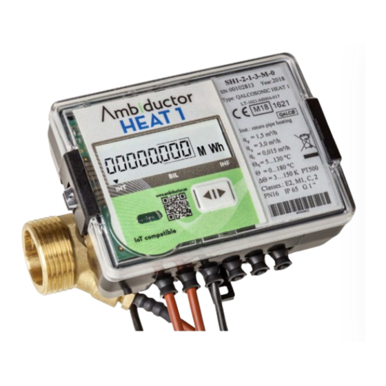
Ambiductor HEAT 1 Manuale di istruzioni per il funzionamento e il montaggio - Pagina 15
Sfoglia online o scarica il pdf Manuale di istruzioni per il funzionamento e il montaggio per Strumenti di misura Ambiductor HEAT 1. Ambiductor HEAT 1 20.

Technical data
Accuracy class
2 according LST EN1434-1:2007
Units, energy
kWh, MWh, GJ, Gcal
Max value, power
2,63 MW
Flow measurement
The meters are provided with dynamic measuring range R100
and R250, i.e. qp = qi x 100 or qp = qi x 250. R250 is only
available for qp 1.5, 2.5, 6.0 and 15 m3 / h.
Flow rate (m
/h)
3
Nom. qp
Max qs
Min qi*
0,6
1,2
1,2
1,5
3,0
0,015/0,0060
3,0
0,015/0,0060
3,0
2,5
5,0
0,025/0,010
5,0
0,025/0,010
3,5
7,0
6,0
12
0,060/0,024
10
20
0,040/0,10
15
30
0,15/0,060
25
50
40
80
60
120
*) Minimum values are R100 / R250
Temperature limits for the liquid
•
For flow sensors qp 2.5 m3 / h 5 ° C .... 130 ° C
•
For flow sensors qp ≥ 3.5 m3 / h 10 ° C .... 130 ° C
Note: For liquid temperature below 90 ° C, the integra-
tor can remain on the flow sensor or be mounted on the
wall. For liquid temperature above 90 ° C, the integrator
must be mounted on the wall.
Connection cable length between the integrator and the flow
sensor 1.2 m.
Maximum working pressure 16 bar (PN16).
The meter's behavior, when the flow rate exceeds the maxi-
mum flow qs:
•
Linear at flow rate up to q = 1.2 ∙ qs
•
Constant at flow rate q> 1.2 ∙ qs (q = 1.2 ∙ qs is as-
sumed for heat energy calculation).
The error message "Maximum allowable flow rate value
is exceeded" is displayed
Temperature measurement
Temperature range, cal-
culator
Temperature difference
range
Temperature sensors
Platinum resistance tempe-
rature sensors Pt500
Alternative temperatur
sensors
For threaded meters G20,
G25 and G32
Ambiductor AB reserves the right to make changes without prior notice. Reprinting or copying this publication without permission is prosecuted.
Connection
Start
0,0060
0,003
0,0060
0,003
0,003
0,003
0,015
0,005
0,005
0,005
0,035
0,017
0,012
0,02
0,03
0,25/0,10
0,05
0,40/0,16
0,08
0,60/0,24
0,12
0°C .... 180°C
2K .... 150K (eller 3K .... 150K)
Pt 500 (according EN60751 and paired
according EN1434 and MI004 in direc-
tive 2014/32/EU)
Pt1000 (on request)
Direct mounted short sensors type DS
according LST EN1434-2
Flow sensors can be supplied for thread connection (up to qp
10 m3 / h) or flange.
Technical data for the flow sensor is presented in the following
table.
Length L
(mm)
G20/G¾"
G25/G1" (and DN20)
G20/G¾"
G25/G1" (and DN20)
G25/G1"
G25/G1"
G25/G1" (and DN20)
G32/G1¼"
G32/G1¼" (and DN25)
G50/G2" (and DN40)
DN50 flange
DN65 flange
DN80 flange
DN100 flange
For all other connections
Cable lengths for 2 wire temperature sensors
Sensor type DS (see above)
Sensor type PL (see above)
LCD Display
The device is equipped with 8-digit LCD (Liquid Crystal Dis-
play) with special symbols to display parameters, units of
measurement and operating modes.
The following information can be displayed: integrated and
instantaneous measured parameters, and archive data and
device configuration.
Display resolution, depending on permanent value flow rate, is
provided in the following table.
Permanent flow rate qp
Resolution volume, m3
Resolution energy, kWh
(MWh)
Resolution energy, Gcal
Resolution energy, GJ
15
Nom. pres-
Pressure
sure PN
drop at qp
(bar)
(kPa)
110
16
190
16
110
16
190
16
130
16
130
16
190
16
260
16
260
16
300
16
270
16
300
16
300
16
360
16
Pocket mounted longer sensors type PL
according LST EN1434-2
1.5m standard (2.5 or 5m on request)
Cable length depending on meter size
(3 up to 10m)
< 6 m3/h
00000,001
0000000,1 kWh
00000,001 Gcal
00000,001 GJ
Weight
(kg)
7,0
1,0
0,90
1,3
17,1
1,0
5,8
1,3
7,2
1,3
19,8
1,3
9,4
1,3
4,0
3,9
10
3,9
18
4,0
12
6,8
20
13
18
14
18
19
≥ 6 m3/h
00000,001
00000,001 MWh
00000,001 Gcal
00000,001 GJ
